M-Series Operator’s Manual 4/9/2015 10-42
Graphics
Intercon features three-dimensional previews of the tool path to be followed when milling the part. You may choose to
display your project in one of two formats: a three-plane display, where the project is shown in each of the XY-, ZX-,
and YZ-planes; or an isometric display, which depicts the project three-dimensionally from an observer's point of
view. To view the graphics, press F8 - Graph from the Main Menu or from any Operation Edit screen.
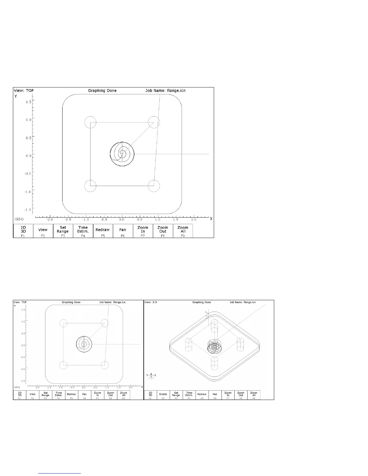
The format of the display will be similar to the following:
The display will consist of arcs and/or lines that make up the tool path followed. Rapid (G0) moves will appear in
Red, linear (G1) and arc (G2, G3) moves will be Yellow, and compensated pass will appear in grey. Canned cycle
operations (except the facing cycle) will also display a gray.
F1 – 2D/3D Pressing F1 - 2D/3D selects the format of the project display. This may take the form of the three-plane
display (2D) or the isometric display (3D).
Three-plane (2D) Isometric (3D)