M-Series Operator’s Manual 4/9/15
9-1
Chapter 9
Probing
Attention!! Refer to the Probe Parameters sections at the end of this chapter before using any
probe.
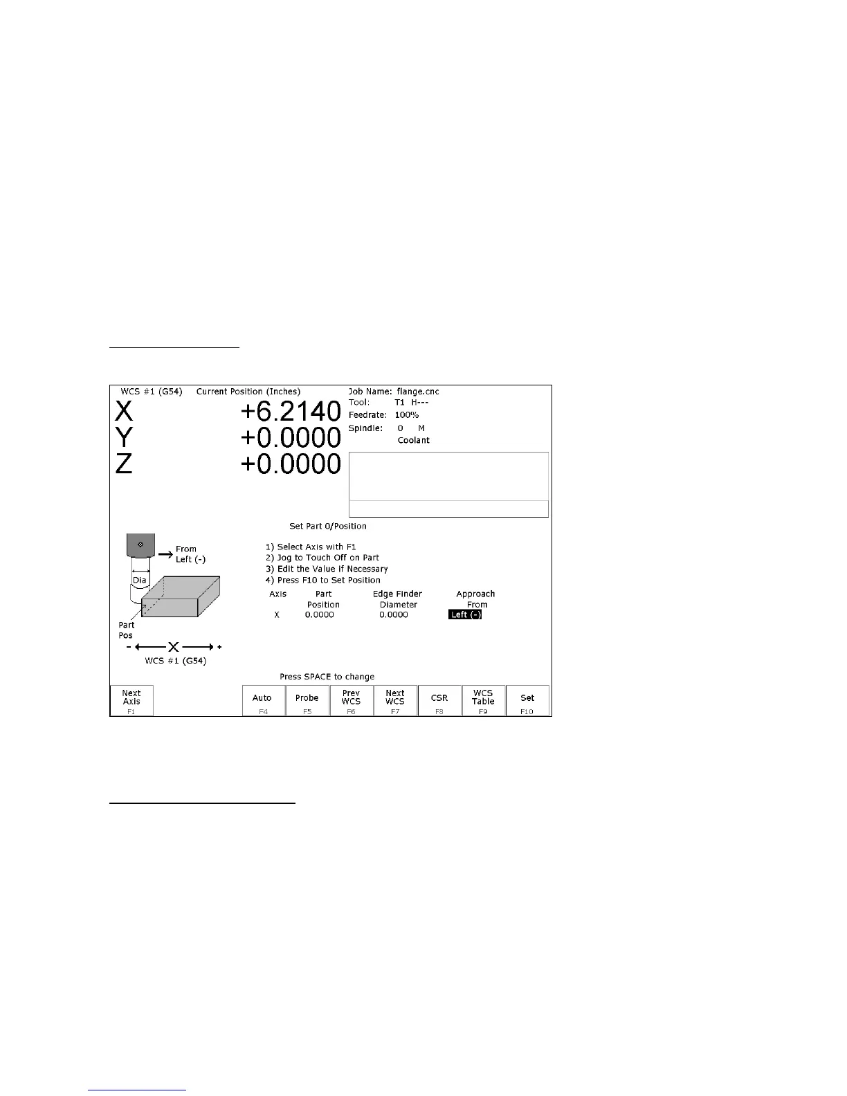
Part Setup with Probing
Single axis, single surface probing is available on the Set Part 0/Position screen using the F4 - Auto key. This
allows you to probe various surfaces to define the part coordinate system. Multi-axis and multi-surface probing
cycles are available on a separate screen, accessible from Set Part 0/Position with the F5 - Probe key or from F4 -
Probe in the digitize screen. These allow you to locate the center points and corners of differently shaped parts.
Brushless motor note: If you experience excessive vibration on a brushless drive system, use Parameter 10 to select
smooth deceleration in probing moves. See Chapter 14 for more information.
WARNING: Before manually jogging any probe, make sure the machine Feedrate is slow (less than 10
in/min) or damage to the probe may result!
Automatically Setting Part 0
Part zero can be found using the probe. Make sure your probe height and diameter offsets are set for the tool
number you assigned to the probe and that parameter 12 is set to that tool number. The Edge Finder Diameter will
be set automatically.
To set part 0 using the probe:
1. Select the current work coordinate system by pressing F6 – Prev WCS or F7 – Next WCS. Then select the axis
you want to probe by pressing F1 – Next Axis.
2. Manually jog the probe about 1/2 inches away from the surface you wish to define. Make sure the approach
direction to the part is set properly. Probe the selected axis by pressing F4 - Auto. When the surface is found, the
control will assume this point to be the new axis 0.