M-Series Operator’s Manual 4/9/15 1-1
Chapter 1
Introduction
Window Description
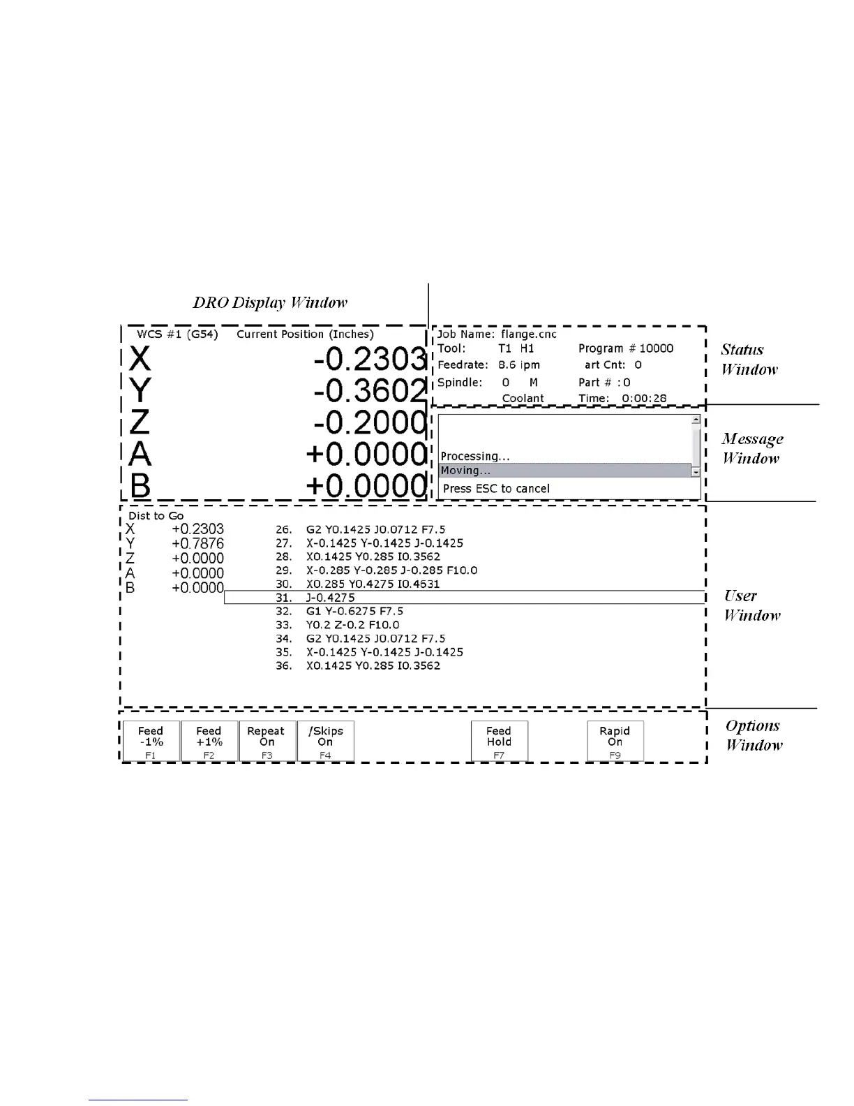
The CNC software display screen is separated into five areas called windows. A sample screen is shown below for
reference. The five windows are the DRO display window, the status window, the message window, the options
window, and the user window. The information that each window displays is described in detail in the following
sections.
DRO display
The DRO display contains the digital read out of the current position of the tool. The display is configurable for
number of axes and desired display units of measure (see Chapter 14). The bars under each axis are the load meters
and represent the amount of power being supplied to the drive for that axis. The display of axis load meters is
configured by machine parameter 143 – see Chapter 14 for specific information.
Distance to Go DRO
The distance to go DRO is located below the main DRO. This display shows the distance to go to complete the
current movement. The display of distance to go is controlled by parameter 143. See Chapter 14 for details. See
also “Hot Keys” in chapter 2.