M-Series Operator’s Manual 4/9/15 2
Operation Description
Setting the part position establishes a coordinate system with an origin at the part zero.
The F1 - Next Axis option selects the axis to be defined next. This field toggles between axis X, Y, Z, 4
th
, and 5
th
Axes. For each axis you will see a graphic description of the parameters to be entered, as well as the corresponding
fields.
Setting up X or Y AXIS
Part Position: enter the value of your part zero position or the offset.
Edge Finder Diameter: enter the diameter of the tool, or edge finder you are using to determine the part zero. The
value entered is stored.
Approach From: Toggle the direction the edge finder or probe is approaching the part.
*Note – Use the arrow keys to toggle between Part Position, Edge Finder Diameter, and Approach From options.
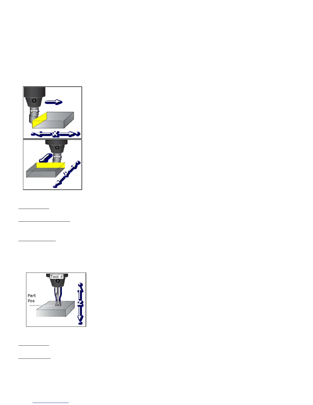
Setting up the Z AXIS
Part Position: enter the value of your part zero position or the offset.
Tool Number: enter the tool number from the Tool Library that corresponds to the tool being used. When the Tool
Number field is set to a value other than zero, the controller uses the Height Offset for that tool from the Tool
Library to calculate the actual position.
Set Part Position
1) Select Axis with F1
2) Jog to Touch Off on Part
3) Edit the Value if Necessary
4) Press F10 to Set Position
Axis Part Edge Finder Approach
Position Diameter from
X 0.0000 0.0000 Left (-)
Set Part Position
1) Select Axis with F1
2) Jog to Touch Off on Part
3) Edit the Value if Necessary
4) Press F10 to Set Position
Axis Part Tool
Position Number
Z 0.0000 0