M-Series Operator’s Manual 4/9/15 1
Chapter 4
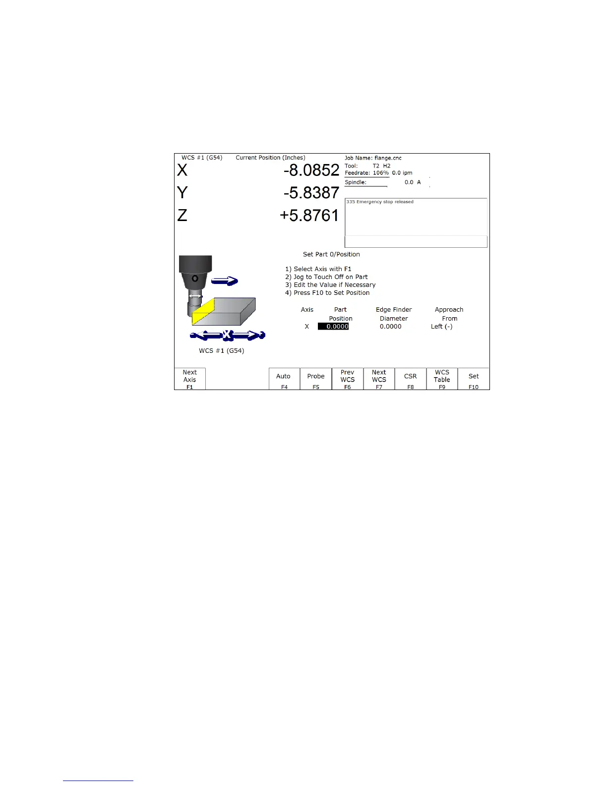
Part Setup
(F1 from Setup)
The Part Setup menu is used to set the part position or the coordinate system origin for the part.
F1 – Next Axis Will toggle to the next axis. If changes were made to the current axis, but not yet accepted, they
will be discarded.
F4 – Auto Uses probe to automatically measure and set part position. Make sure your probe height and diameter
offsets are set for the tool number you assigned to the probe and that parameter 12 is set to that tool
number. See Chapter 9 for more details.
F5 – Probe Will open the probing operations menu. See Chapter 9 for details.
F6 – Prev WCS Will select the previous work coordinate. The position being set will only affect the currently
selected work coordinate.
F7 – Next WCS: will select the next work coordinate. The position being set will only affect the currently selected
work coordinate.
F8 – CSR Will open the CSR menu, which can be used to automatically detect coordinate system rotation. This
function key appears only when the software option for Coordinate System Rotation is unlocked.
F9 – WCS Table Will open the Work Coordinate System (WCS) Configuration screen. See the Work Coordinate
System Configuration section later in this chapter for a complete description.
F10 – Set Will accept the position for the current axis, correcting for edge finder diameter based on the approach
direction if appropriate. It will not automatically advance to the next axis.