M-Series Operator’s Manual 4/9/2015 10-8
F2 - Linear Mill
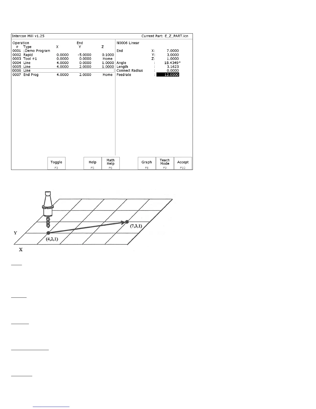
If you press F2 - Linear from the Insert Operation screen, the following screen appears:
The numbers in the different fields on the screen correspond to the following Linear Mill example shown here
graphically:
End: When you first access the linear mill screen, the cursor will be highlighting the first field, End X. This is the X
coordinate of where the cutter will be after the linear move has been completed. Similarly, Y and Z represent the
coordinates of the cutter after the linear move is completed. The angle and length fields will be computed if you
choose to enter the end point of the move.
Angle: The destination may also be specified in terms of a counterclockwise angle from the three o'clock position.
When combined with a length for the current move, the corresponding X and Y coordinates for the destination will be
calculated and placed in the correct fields. The Z destination will remain unchanged, however.
Length: The length of the linear mill. When combined with the angle of the current move, the corresponding X and Y
coordinates for the destination will be calculated and placed in the correct fields. The Z destination will remain
unchanged, however.
Connect Radius: If you are performing two linear mill operations and you wish to have a rounded 'corner' between
them instead of a sharp peak, you may enter the radius of the 'corner' and Intercon will insert an arc between the linear
mill operations. This connect radius also works for blending a line into an arc operation.
Feedrate: Speed at which the cutter moves.