M-Series Operator’s Manual 4/9/15
8-10
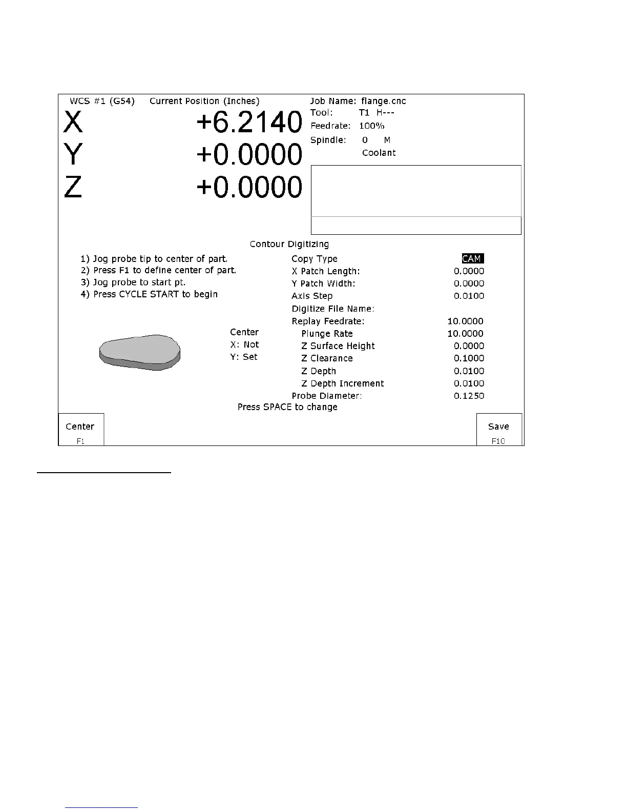
Contour Digitize
(F3 from Digitize Menu)
Contour Digitize Run Setup
To set up a digitizing run, jog the probe tip to the center of the part and hit F1 - Center to assign that as your center
point.
Select CAM for a true CAM shape contour, or Wall for irregular shapes for wall following. Enter the rest of the
parameters for the part and digitizing job as shown below.
Jog the probe to a starting point and press CYCLE START. The control will move the probe toward the center line
in the +/- X direction until it comes into contact with the part. At each point of contact, the X and Y coordinates
will be recorded in the data file.
The probe will continue around the contour until it returns to the starting point to complete the cycle. Based on the
starting point, and the first point of contact, the digitize software will determine if the contour is internal or
external.
Important note: When probing an external contour, make sure the probe comes in contact with part on the first
move. If it doesn’t, the software will compensate to the outside of the part as if it were an internal contour causing
your part to come out larger than you want it to be.