M-Series Operator’s Manual 4/9/15
8-2
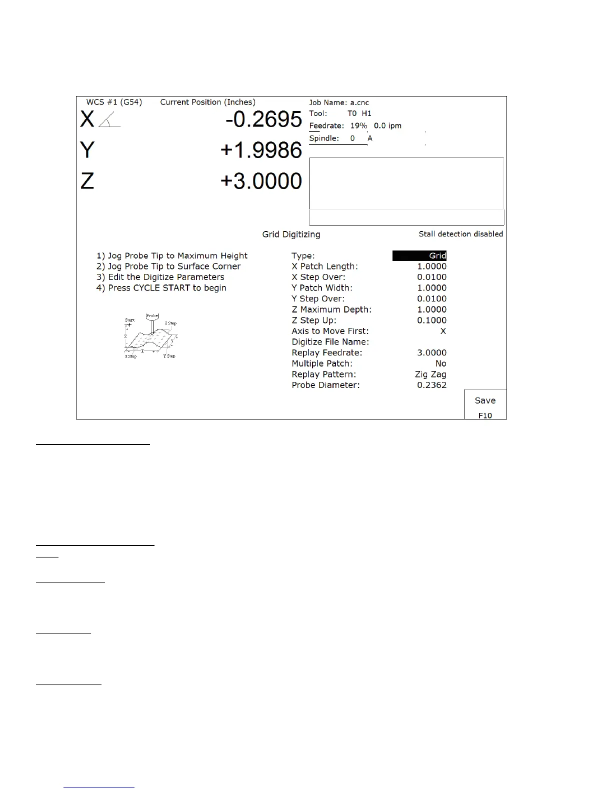
Grid Digitize
(F1 from Digitize Menu)
Grid Digitize Run Setup
To set up a digitizing run, edit the parameters shown and then press CYCLE START. The control will move
through the area to be digitized in a rectangular pattern. At each X-Y point in the pattern, it will measure the Z
height of the sample surface, and record the coordinates in the data file.
Digitizing begins at the current tool position when the CYCLE START button is pressed. This position should be
in one corner of the digitize area, at a Z position higher than any point on the surface.
Grid Digitize Parameters
Type: This sets the algorithm for digitizing: either regular Grid or Surface Following.
X Patch Length: The length of the area to be digitized, along the X-axis. A positive value will cause digitizing to
proceed in the X+ direction from the starting point; a negative value will cause digitizing to proceed in the X-
direction. If the value is 0, then digitizing will collect just one stripe along Y.
X Step Over: The distance to move between points on the X-axis. A smaller value should be used for a fine
digitize along the X-axis. A larger value should be used for a rough digitize along the X-axis. This distance should
be a positive incremental value.
Y Patch Width: The width of the area to be digitized, along the Y-axis. A positive value will cause digitizing to
proceed in the Y+ direction from the starting point; a negative value will cause digitizing to proceed in the Y-
direction. If the value is 0, then digitizing will collect just one stripe along X.