M-Series Operator’s Manual 4/9/15 8
F1 - Orient is used to select the orientation for the CSR measurement. There are four possible orientations, which
are: from the front (pictured above), the back, and the left and right sides.
F2 - Manual is used to determine the CSR angle without probing. The user jogs an edge finder to two positions
along one wall. These positions will be used for computing the CSR angle.
F3 - Zero Cur is used to set the CSR angle for the current WCS to zero.
F4 - Zero All is used to set all CSR angles to zero.
F5 – Probe Will open the probing operations menu. See Chapter 9 for details.
F6 - Prev WCS and F7 - Next WCS are used to cycle through the available WCS systems.
F8 – MDI The MDI menu allows you to a single line command such as: G1 X2 Y3 F20
F9 - WCS Table is a shortcut to the Work Coordinate System Configuration Screen described above.
The instructions on how to perform a CSR measurement are numbered on the screen.
Distance: The distance the X-axis (in front or back orientation) or Y-axis (in right or left side orientation) will
move to probe the second point. If the distance is negative, the axis will be moved in the negative direction.
Clearance Amount: The distance the Z-axis will be moved upward when moving between the first probe point and
the second probe point. The clearance move will only be made when using the “Auto” option of the Movement
between Points.
Movement between Points can be toggled between Jog and Auto modes. In Auto mode, the clearing moves are
made automatically as well as the move to the second point. In Jog mode, a prompt will be displayed in the center
of the screen after the first point is probed.
Transformed WCS (TWCS=Yes)
This section only applies to Articulated Head machines with the TWCS feature enabled via Parameter 166 (see
Chapter 14 for more information on setting Parameter 166). On such a machine, when a WCS has a setting of
TWCS=Yes, this is then called a transformed WCS (abbreviated as TWCS).
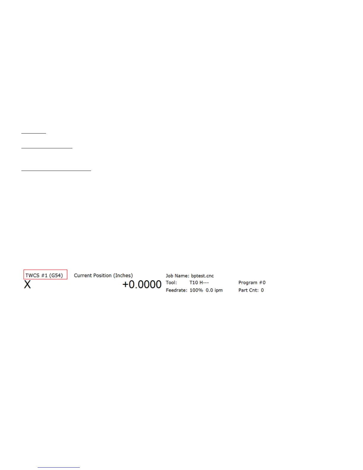
When a TWCS is selected, the DRO will show axis positions based on the TWCS’s frame of reference. In other
words, the shown positions are transformed based on the position of the B axis (5
th
axis). Furthermore, the WCS
label will be shown as “TWCS” to indicate that the currently selected WCS is indeed transformed.
Also, when the Probing Cycles are run with a TWCS selected, the results shown will be based on the TWCS frame
of reference.
Ordinary 3 axis moves types performed while running a CNC program with a TWCS selected will be automatically
transformed. Such move types include:
• G0, G1, G2, G3
• Protected move probing functions M115, M116, M125, M126
• Canned Cycles G73, G74, G76, G81, G82, G83, G84, G85, G89
• M25
• Moves that involve CSR and Cutter Compensation
However, moves that will not be transformed are:
• Homing moves M91/M92
• Move to switch M105/M106
• Move axis by counts M128