M-Series Operator’s Manual 4/9/15 3
Example 1 (You are using the reference tool to find the Z-axis part zero):
Set Tool Number to 0: setting the Tool Number to zero tells the controller that you are using the reference tool.
Example 2 (You are using a tool other than the reference tool, and not a ball nose cutter):
Set Tool Number to a number tool that is assigned in the tool library (make sure its height offset is set).
Example 3 (You are using a ball nose cutter, other than the reference tool):
Set Part Position to the position of the surface plus the nose radius of the ball nose cutter, set Tool Number to the
number this tool is assigned in the tool library.
The Tool and Offset libraries must be up to date before setting the Z-axis Part Zero.
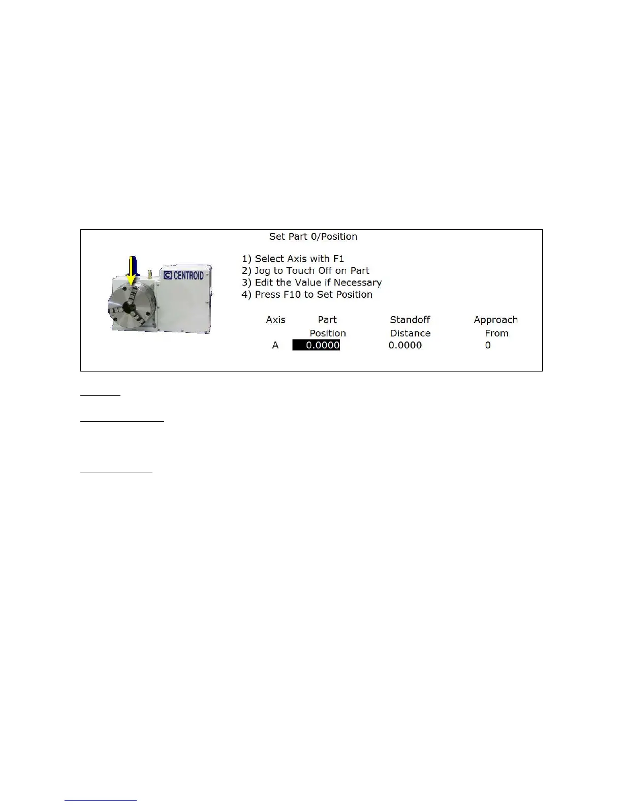
Setting up the 4
th
or 5
th
AXIS***
Position: enter the value of your part zero position or the offset.
Standoff Distance: this field is a generic parameter. Its physical meaning will depend on the specific nature of your
machine's fourth axis. It is the distance between the center of the tool and the point at which the tool is touching the
part surface.
Approach from: enter the direction the edge finder is approaching the part from. Enter the correct direction given
the nature of your 4th-Axis.
Using Multiple Work Coordinate Systems
If you will be using multiple work coordinates, you must set the part position separately for each work coordinate.
Follow the instructions above to set the position for each axis in the first coordinate system. Then move to the next
fixture and press F6 – Prev WCS to select the previous work coordinate or F7 – Next WCS to select the next work
coordinate. The currently selected coordinate system is displayed below the axis picture on the Part Setup screen.
It is also displayed above the DRO at all times. For a description on setting up each work coordinate, see the Work
Coordinate System Configuration section later in this chapter.
.
NOTICE
This procedure does NOT apply to tilt table setup.