M-Series Operator’s Manual 4/9/15
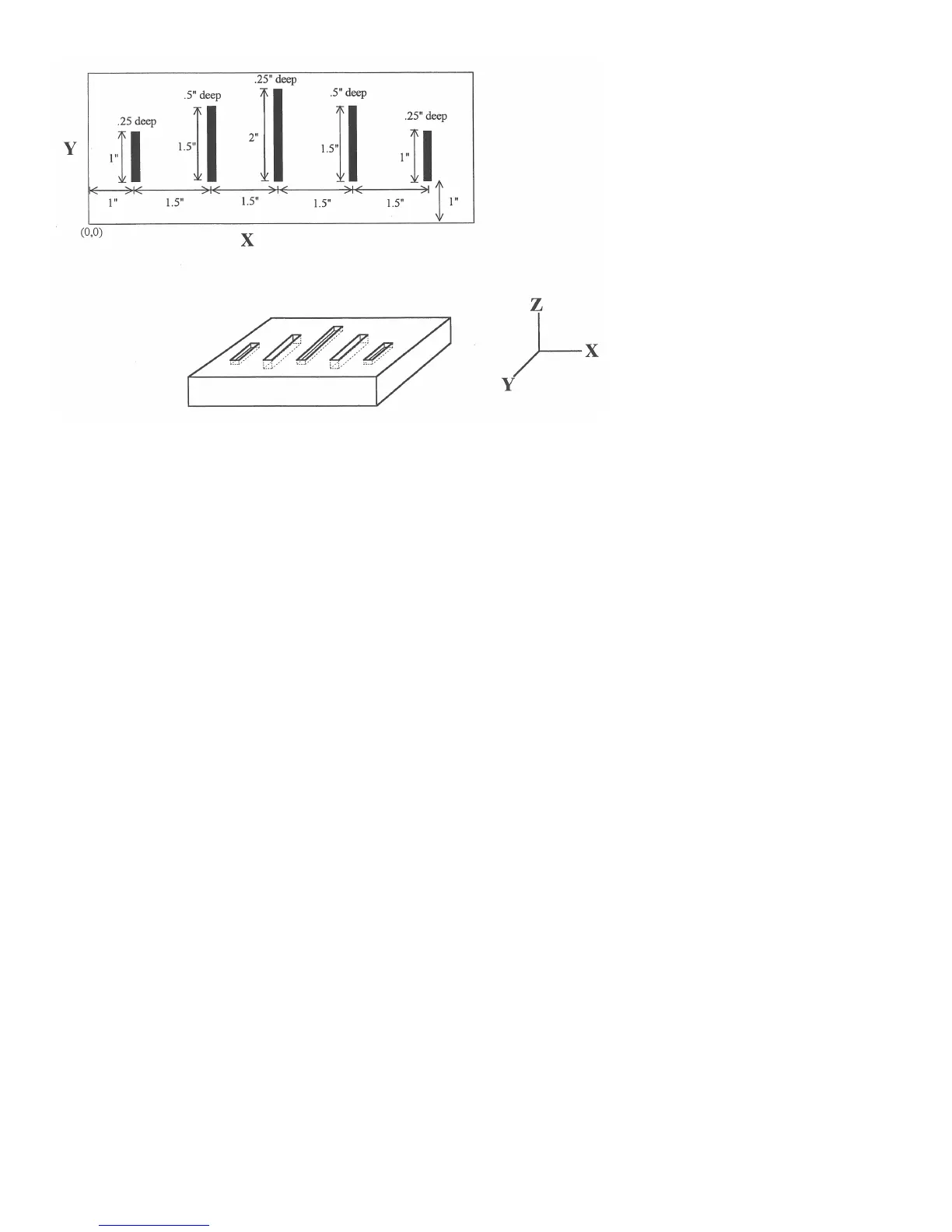
The macro variables would handle the length in the Y direction and depth in the Z direction:
O0002
G90 G1 Z0 F30 ; Linear move to Z0
Z#Z F5 ; Cut to variable depth
G91Y#Y F10 ; Cut variable length
G90 G0 Z0.1 ; Retract
The main program would call this macro five times, each time specifying the depth and length required.
: Main Program
G90 G0 X1 Y1 Z0.1 ; Move to first notch
G65 P0002 L1 Y1 Z.25 ; Call macro and assign Y=1" and Z=.25"
G90 G0 X2.5 Y1 ; Move to second notch
G65 P0002 L1 Y1.5 Z.5 ; Call macro and assign Y=1.5" and Z=.5"
G90 G0 X4 Y1 ; Move to third notch
G65 P0002 L1 Y2 Z.25 ; Call macro again
G90 G0 X5.5 Y1 ; Move to fourth notch
G65 P0002 L1 Y1.5 Z.5 ; Call macro again
G90 G0 X7 Y1 ; Move to fifth notch
G65 P0002 L1 Y1 Z.25 ; Call macro again
: End program
G68, G69 - Coordinate Rotation on/off
G68 rotates program G-codes a specified angle R. G68 rotates all positions, lines, and arcs until a G69 is entered.
The center of rotation can be specified by X, Y and Z values (X, Y for G17 plane). If the center is not specified
then a default center of rotation is used as determined by machine parameter #2 (see Chapter 14 for parameter #2).
The default plane of rotation is G17 (X, Y).