M-Series Operator’s Manual 4/9/15
F7 – Scales This menu lets you set up scale encoders for the purpose of applying scale encoder correction to one or
more axes.
NOTICE
The Scale Settings should not be changed without contacting your dealer. Corrupt or
incorrect values could adversely affect the accuracy of the positioning of your machine.
Axis and Label are for informational purposes to indicate on which axis the scales will be applied. These values cannot
be modified on this screen.
Input is the scale encoder number based on the map shown on parameters 308-315. Numbers 1-6 are on the MPU11
and 7-14 are on Optic4 drives. If spare headers are available on the Optic4, they can be used for scale feedback.
Enabled Y enables the scale and N disables the scale.
Scale Counts/Unit is the number of counts of the scale per unit of measurement. This value should come directly from
the scale data sheet and should be entered in the control units. If the control is in inches, then the value should be
entered in inches.
Ratio is calculated as [(Motor Encoder Counts per Rev. * Motor Rev. per Unit) / Scale Counts per Unit] and cannot be
modified. It shows how close the counts/unit are between the motor encoder and scale encoder.
Deadband is the number of encoder counts away from the commanded position that the scale position can be before
compensating. Typically an integer multiple from 1 to 3 times the Ratio should be used.
Velocity is the number of motor encoder counts / interrupt at which the Scales should adjust the position. Typically a
value of 0.5 is a good starting value. To figure out a value to use based on a units/min. speed you need to convert it.
The equation is [units/min. * Motor Encoder Counts per Rev. * Rev. per unit * (1min/60 sec.) * (1sec./4000 int)].
Due to the nature of scale feedback it is inherently an oscillator and by adjusting the Deadband and Velocity that
oscillation can be kept to a minimum.
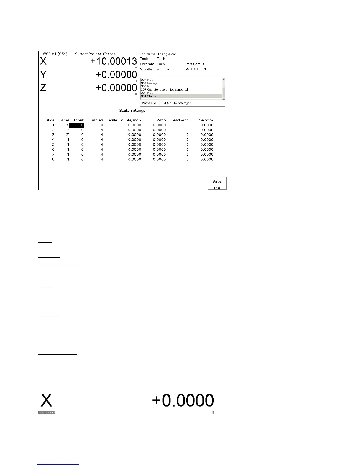
Scale Indicator Changing the Input, Enabled, or Scale Counts/Unit fields will cause scale compensation to be
temporarily disabled. Scale compensation is also temporarily disabled during homing moves. Even though the scale
is enabled in the menu, scale compensation will be disabled until the axis is rehomed. When a scale is configured for
an axis, a scale indicator appears below the axis label on the DRO. It will have a green background when the scale is
enabled and a red background when the scale is disabled.