M-Series Operator’s Manual 4/9/15
Parameter 270-271 – XY Skew Correction
These parameters work together to correct XY position skew, which can occur if the X axis is not exactly
perpendicular to the Y axis (or vice versa). To turn on XY skew correction, use the chart and follow the skew
measurement procedure described below. To turn off XY skew correction, set both parameters to 0.
Parameter
Symbol
Description
270 S +/- X skew deviation from perfect X and perfect Y
271 L Y length over which to apply a position correction to counteract a
skew of amount S
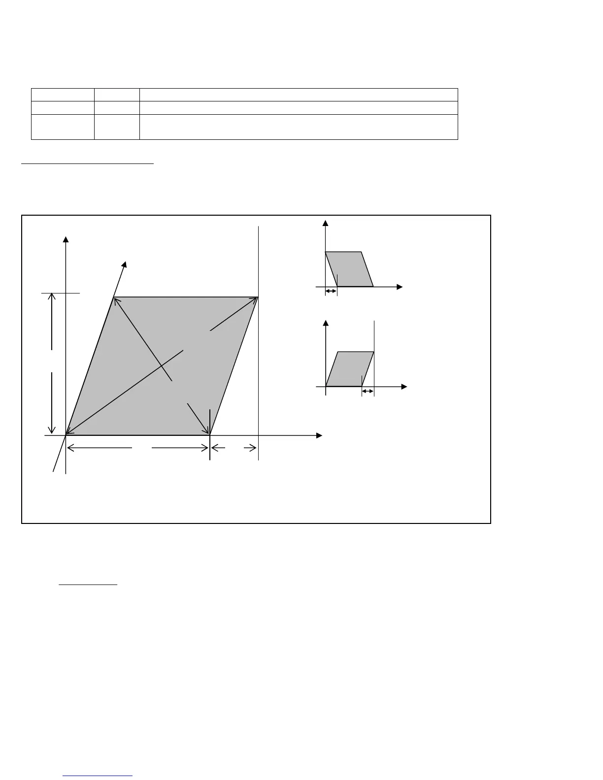
Skew Measurement Procedure:
Program a sufficiently large L x L square and cut it on a scrap piece of material using the machine in question. Put this
“square” piece against a true square corner and measure the skew S. If the square is leaning to the left, then S is
negative; if it is leaning to the right, then S is positive. Set Parameter 270=S and Parameter 271=L.
If you have trouble directly measuring S, you can calculate it by measuring the diagonals D1 and D2, and then using
the following formula:
Parameter 278 – Spindle Speed Display Precision
This sets the number of digits after the decimal point to display on the Spindle Speed display in the Status Window. A
setting of 0 means to show whole number spindle speeds.
D1
D2
Corrected Y Axis
L
S
S = positive (+)
S = negative (-)
L
(Note: The skew shown above is exaggerated for illustration purposes.
Actual skew usually is not visually detectable unless it is measured.)
S =