M-Series Operator’s Manual 4/9/15 5
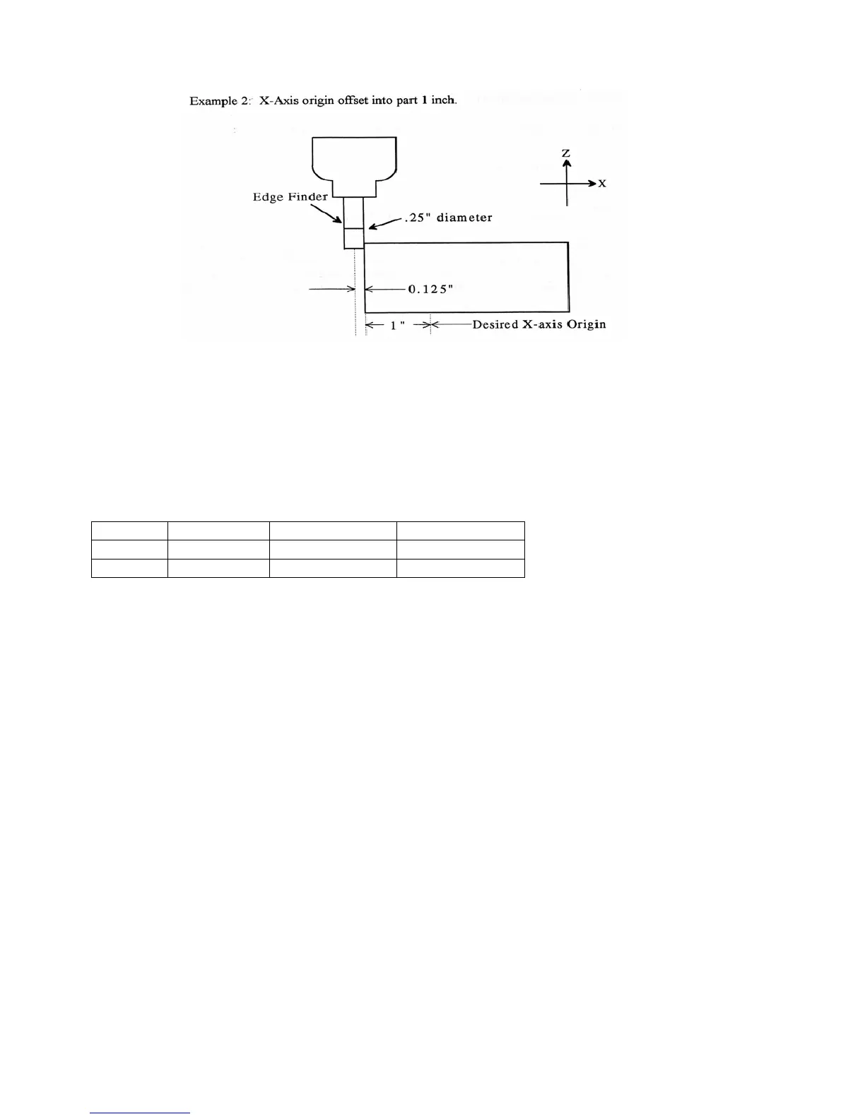
Example 2: X-Axis origin offset into part 1 inch.
If you wanted the origin offset 1 inch into the part:
1. Move the Edge Finder to the left edge of the part
2. Press F1 – Next Axis until the axis field displays 'X'
3. Move the cursor to the Part Position field
4. Type -1 and press ENTER
5. Type .25 and press ENTER
6. Press SPACE until Left (-) is displayed
7. Press F10 - Set to accept the value
Axis Part Edge Finder Approach
Position Diameter from
X -1 0.25 Left (-)
The Position value is relative to the current position of the Edge Finder. Part position equals -1.0 since the Edge
Finder is positioned 1 inch to the left (minus direction) of where you want the X-axis origin.
Another way to view the Part Position value is to assume the origin is already set at 1 inch into the part. In this
case, the Edge Finder would have to move -1 inches from where the origin is to get to the left edge of the part.
The Edge Finder is approaching the part from the -X direction and has a diameter of .25 inches. Once this data is
entered and F10 - Set is pressed, the X-axis DRO display will read -1.125. This means the center of the Edge
Finder is sitting to the left (minus) of the origin by 1.125 inches. The X-axis origin is now 1 inch into the part.
This value is computed by: Position (Approach from) Edge Finder Diameter / 2.
Where (Approach from) is the sign of the approach direction. In other words, if the approach direction is minus,
then the value is:
Position - Edge Finder Diameter / 2 = -1.0 - .25 / 2 = -1.125