M-Series Operator’s Manual 4/9/15
8-5
3. A good technique for calculating Z maximum depth is to touch off the lowest surface of the part to be digitized
and set the part zero's Z value to Z0. Then jog the probe tip to a point higher than the highest surface of the part to
be digitized. Note the displacement in the Z-axis. Again, set this Z height to Z0 and use the noted displacement for
the Z maximum depth.
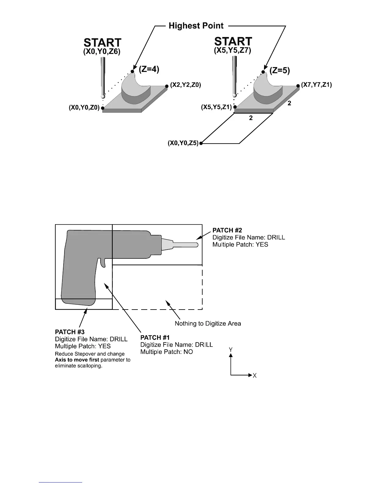
4. Multiple patches are useful in the following situations: completing a canceled digitize run, digitizing parts with
large areas that contain nothing to be digitized (shown below), and patching vertical walls to eliminate scallops
caused by the cutting tool.
The drill shown in the previous example is L-shaped. Therefore, it can be digitized faster and more efficiently
using three rectangular patches than digitizing the complete area with a single patch.
Digitizing the entire part and then adding multiple small patches along the walls can avoid vertical wall scalloping.
If a vertical wall extending along the X axis needs to be cleared of scallops, just add a small patch running the
length of the wall. Set the “Axis to Move First” parameter to Y. This will clear the scallops.