15-8
Catalyst 3750 Metro Switch Software Configuration Guide
78-15870-01
Chapter 15 Configuring MSTP
Understanding RSTP
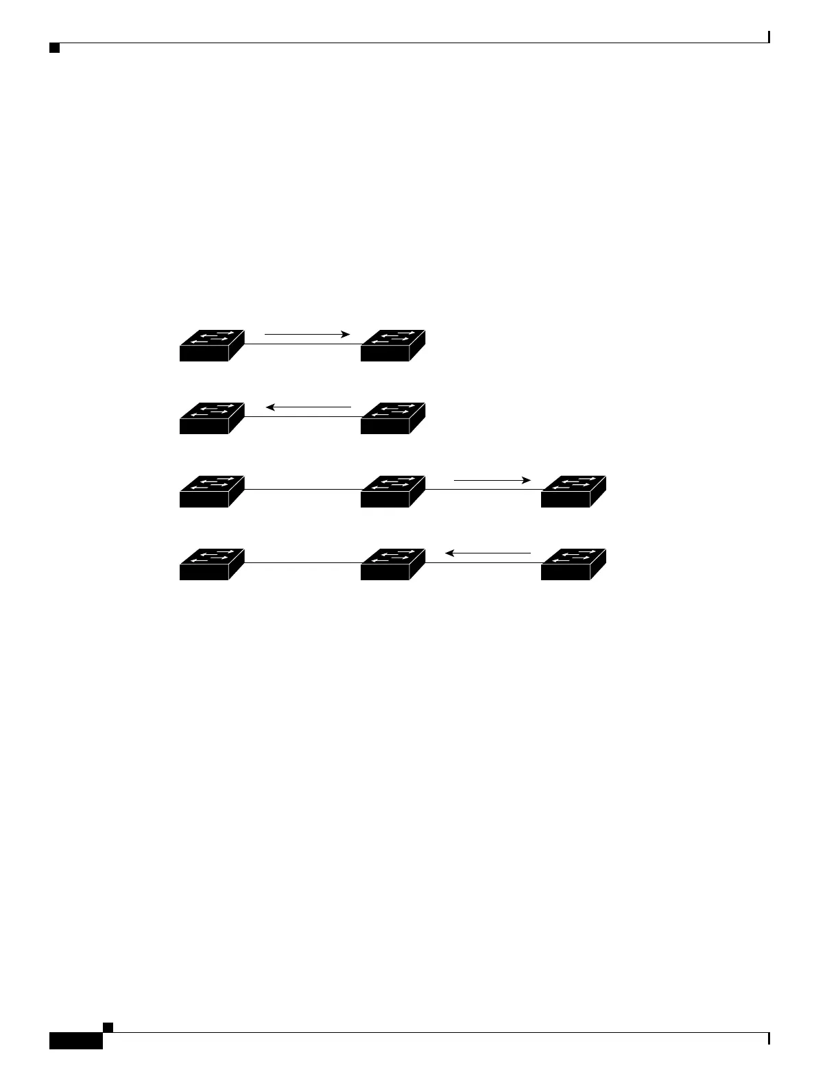
When Switch C is connected to Switch B, a similar set of handshaking messages are exchanged.
Switch C selects the port connected to Switch B as its root port, and both ends immediately
transition to the forwarding state. With each iteration of this handshaking process, one more switch
joins the active topology. As the network converges, this proposal-agreement handshaking
progresses from the root toward the leaves of the spanning tree.
The switch learns the link type from the port duplex mode: a full-duplex port is considered to have
a point-to-point connection; a half-duplex port is considered to have a shared connection. You can
override the default setting that is controlled by the duplex setting by using the spanning-tree
link-type interface configuration command.
Figure 15-2 Proposal and Agreement Handshaking for Rapid Convergence
Synchronization of Port Roles
When the switch receives a proposal message on one of its ports and that port is selected as the new root
port, the RSTP forces all other ports to synchronize with the new root information.
The switch is synchronized with superior root information received on the root port if all other ports are
synchronized. An individual port on the switch is synchronized if
• That port is in the blocking state.
• It is an edge port (a port configured to be at the edge of the network).
If a designated port is in the forwarding state and is not configured as an edge port, it transitions to the
blocking state when the RSTP forces it to synchronize with new root information. In general, when the
RSTP forces a port to synchronize with root information and the port does not satisfy any of the above
conditions, its port state is set to blocking.
After ensuring all of the ports are synchronized, the switch sends an agreement message to the designated
switch corresponding to its root port. When the switches connected by a point-to-point link are in agreement
about their port roles, the RSTP immediately transitions the port states to forwarding. The sequence of events
is shown in Figure 15-3.
Proposal
Switch A Switch B
FF
RPDP
FF
RPDP
FF
RPDP
FF
RPDP
Switch C
88760
Agreement
Root
Designated
switch
Root
Designated
switch
Proposal
Root
Designated
switch
Agreement
DP = designated port
RP = root port
F = forwarding