26-66
Catalyst 3750 Metro Switch Software Configuration Guide
78-15870-01
Chapter 26 Configuring QoS
Configuring Standard QoS
This example shows how to map DSCP values 0 to 6 to ingress queue 1 and to threshold 1 with a drop
threshold of 50 percent. It maps DSCP values 20 to 26 to ingress queue 1 and to threshold 2 with a drop
threshold of 70 percent.
Switch(config)# mls qos srr-queue input dscp-map queue 1 threshold 1 0 1 2 3 4 5 6
Switch(config)# mls qos srr-queue input dscp-map queue 1 threshold 2 20 21 22 23 24 25 26
Switch(config)# mls qos srr-queue input threshold 1 50 70
In this example, the DSCP values (0 to 6) are assigned the WTD threshold of 50 percent and will be
dropped sooner than the DSCP values (20 to 26) assigned to the WTD threshold of 70 percent.
Allocating Buffer Space Between the Ingress Queues
You define the ratio (allocate the amount of space) with which to divide the ingress buffers between the
two queues. The buffer and the bandwidth allocation control how much data can be buffered before
packets are dropped.
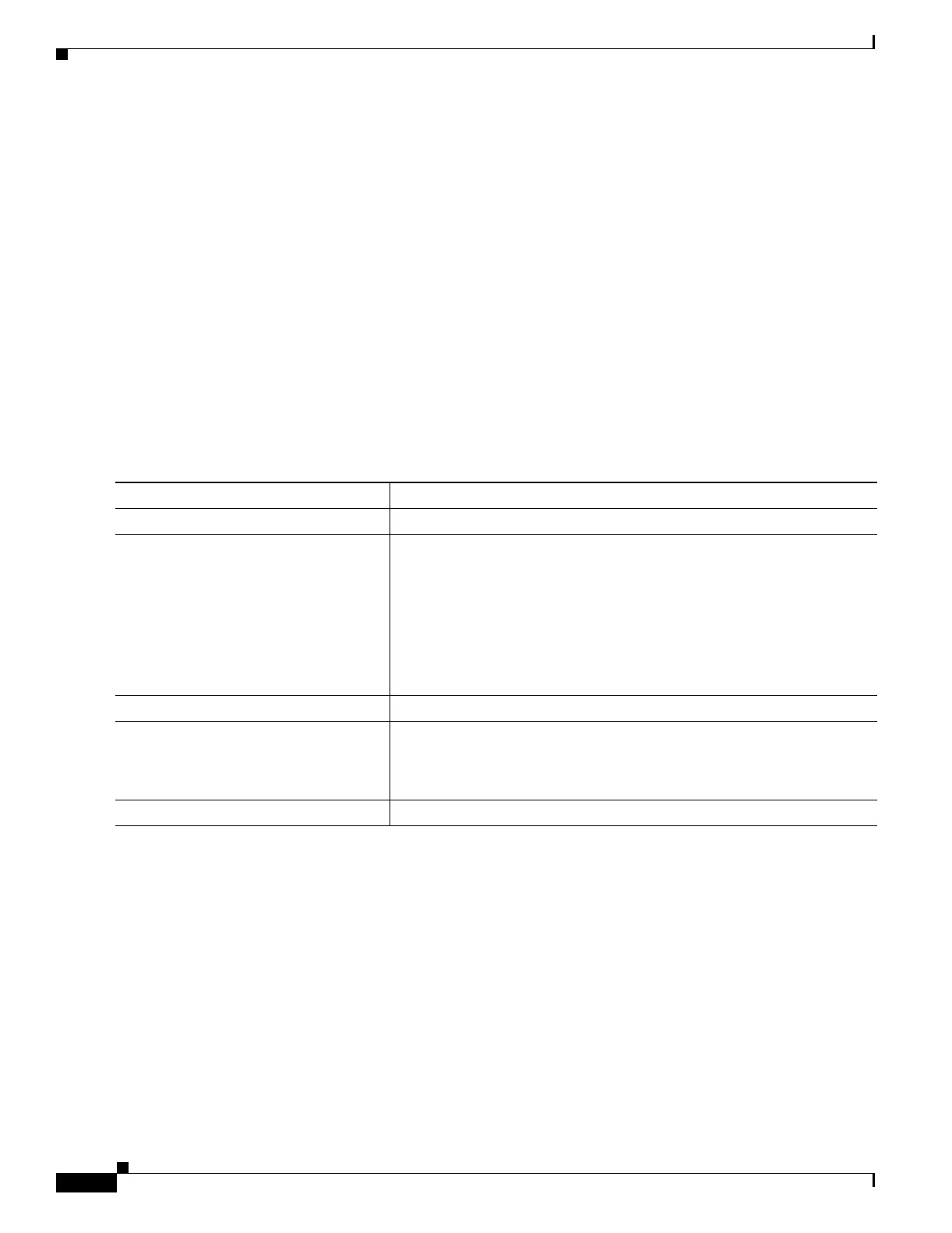
Beginning in privileged EXEC mode, follow these steps to allocate the buffers between the ingress
queues. This procedure is optional.
To return to the default setting, use the no mls qos srr-queue input buffers global configuration
command.
This example shows how to allocate 60 percent of the buffer space to ingress queue 1 and 40 percent of
the buffer space to ingress queue 2:
Switch(config)# mls qos srr-queue input buffers 60 40
Command Purpose
Step 1
configure terminal Enter global configuration mode.
Step 2
mls qos srr-queue input buffers
percentage1 percentage2
Allocate the buffers between the ingress queues
By default 90 percent of the buffers are allocated to queue 1, and 10
percent of the buffers are allocated to queue 2.
For percentage1 percentage2, the range is 0 to 100. Separate each value
with a space.
You should allocate the buffers so that the queues can handle any inbound
bursty traffic.
Step 3
end Return to privileged EXEC mode.
Step 4
show mls qos interface buffer
or
show mls qos input-queue
Verify your entries.
Step 5
copy running-config startup-config (Optional) Save your entries in the configuration file.

 Loading...


