30-17
Catalyst 3750 MetroSwitch Software Configuration Guide
78-15870-01
Chapter 30 Configuring MPLS and EoMPLS
Enabling EoMPLS
This example shows how to configure an EoMPLS tunnel between switch PE1’s VLAN 3 interface and
PE2’s VLAN 4 interface.
PE1 has an IP address 10.0.0.1/32, and PE2 has IP address 20.0.01/32. Both PE routers are configured
with an MPLS connection to the MPLS core. The VC ID is 123.
Enter these commands on the PE1 switch:
Switch(config)# interface loopback0
Switch(config-if)# ip address 10.10.10.10 255.255.255.255
Switch(config-if)# exit
Switch(config)# interface vlan 3
Switch(config-if)# mpls ip
Switch(config-if)# mpls l2transport route 20.0.0.1 123
Enter these commands on the PE2 switch:
Switch(config)# interface loopback0
Switch(config-if)# ip address 20.20.20.20 255.255.255.255
Switch(config-if)# exit
Switch(config)# interface vlan 4
Switch(config-if)# mpls ip
Switch(config-if)# mpls l2transport route 10.0.0.1 123
Packet Flow in an EoMPLS Network
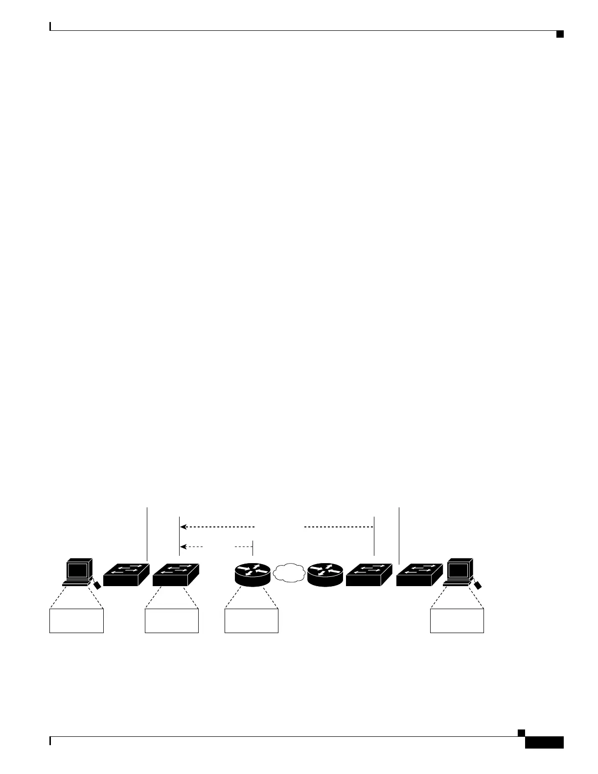
Figure 30-5 is an example of packet flow in an EoMPLS network. A customer port on PE1 is configured
for a per-port EoMPLS tunnel to a remote customer port on PE2. This allows the two physically
separated customer switches (A and B) connected to these ports to appear as if they are directly
connected on the same physical LAN.
The EoMPLS tunnel is configured with the IP address of Switch B and a VC ID that is associated with
the remote customer port. PE1 establishes a tunnel LSP with PE2 by using a label advertised with LDP
by Router A, which is connected to the ES port of PE1. PE1 then establishes a targeted LDP session to
PE2 to advertise the VC label associated with the VC ID. When PE2 is configured with the EoMPLS
tunnel, it also establishes a targeted LDP session to advertise the VC label it associated to the VC ID.
This establishes an EoMPLS tunnel between the two ES ports on switch PE1 and switch PE2.
Figure 30-5 Sample EoMPLS Packet Flow
Assume that Host A is connected to the customer switch on VLAN 3 that has a trunk port connected to
PE1 configured for 802.1Q tagging. Host A sends a packet to Host B, using the specific values of MAC
addresses, labels, and VLANs shown in the figure. The customer switch tags the host packet and
forwards it over the trunk port to PE1.
VLAN 7
Host
A
PE1
Router B
Remote Site
VC Label
EoMPLS Tunnel
101100
MPLS
Customer
switch
A
Customer
switch
B
Host MAC
address: 1
SVI MAC
address: 2
Host
B
Host MAC
address: 4
PE2Router
A
Router MAC
address: 3
Tunnel
Label

 Loading...


