18-2
Catalyst 3750 Metro Switch Software Configuration Guide
78-15870-01
Chapter 18 Configuring Port-Based Traffic Control
Configuring Storm Control
Note When the storm control threshold for multicast traffic is reached, all multicast traffic except control
traffic, such as bridge protocol data unit (BDPU) and Cisco Discovery Protocol (CDP) frames, are
blocked. However, the switch does not differentiate between routing updates, such as OSPF, and regular
multicast data traffic, so both types of traffic are blocked.
When storm control is enabled, the switch monitors packets passing from an interface to the switching
bus and determines if the packet is unicast, multicast, or broadcast. The switch monitors the number of
broadcast, multicast, or unicast packets received within a 200-millisecond time interval, and when a
threshold for one type of traffic is reached, that type of traffic is dropped. This threshold is specified as
a percentage of total available bandwidth that can be used by broadcast (multicast or unicast) traffic.
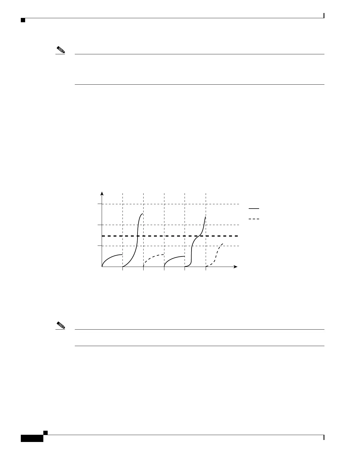
The graph in Figure 18-1 shows broadcast traffic patterns on an interface over a given period of time. The
example can also be applied to multicast and unicast traffic. In this example, the broadcast traffic being
forwarded exceeded the configured threshold between time intervals T1 and T2 and between T4 and T5.
When the amount of specified traffic exceeds the threshold, all traffic of that kind is dropped for the next time
period. Therefore, broadcast traffic is blocked during the intervals following T2 and T5. At the next time
interval (for example, T3), if broadcast traffic does not exceed the threshold, it is again forwarded.
Figure 18-1 Broadcast Storm Control Example
The combination of the storm-control suppression level and the 200-millisecond time interval control
the way the storm control algorithm works. A higher threshold allows more packets to pass through. A
threshold value of 100 percent means that no limit is placed on the traffic. A value of 0.0 means that all
broadcast, multicast, or unicast traffic on that port is blocked.
Note Because packets do not arrive at uniform intervals, the 200-millisecond time interval during which traffic
activity is measured can affect the behavior of storm control.
The switch continues to monitor traffic on the port, and when the utilization level is below the threshold
level, the type of traffic that was dropped is forwarded again.
You use the storm-control interface configuration commands to set the threshold value for each traffic
type.
Total
number of
broadcast
packets
or bytes
Forwarded traffic
0T1
Threshold
T2 T4 T5
46651
T3 Time
Blocked traffic