25-36
Catalyst 3750 Metro Switch Software Configuration Guide
78-15870-01
Chapter 25 Configuring Network Security with ACLs
Using VLAN Maps with Router ACLs
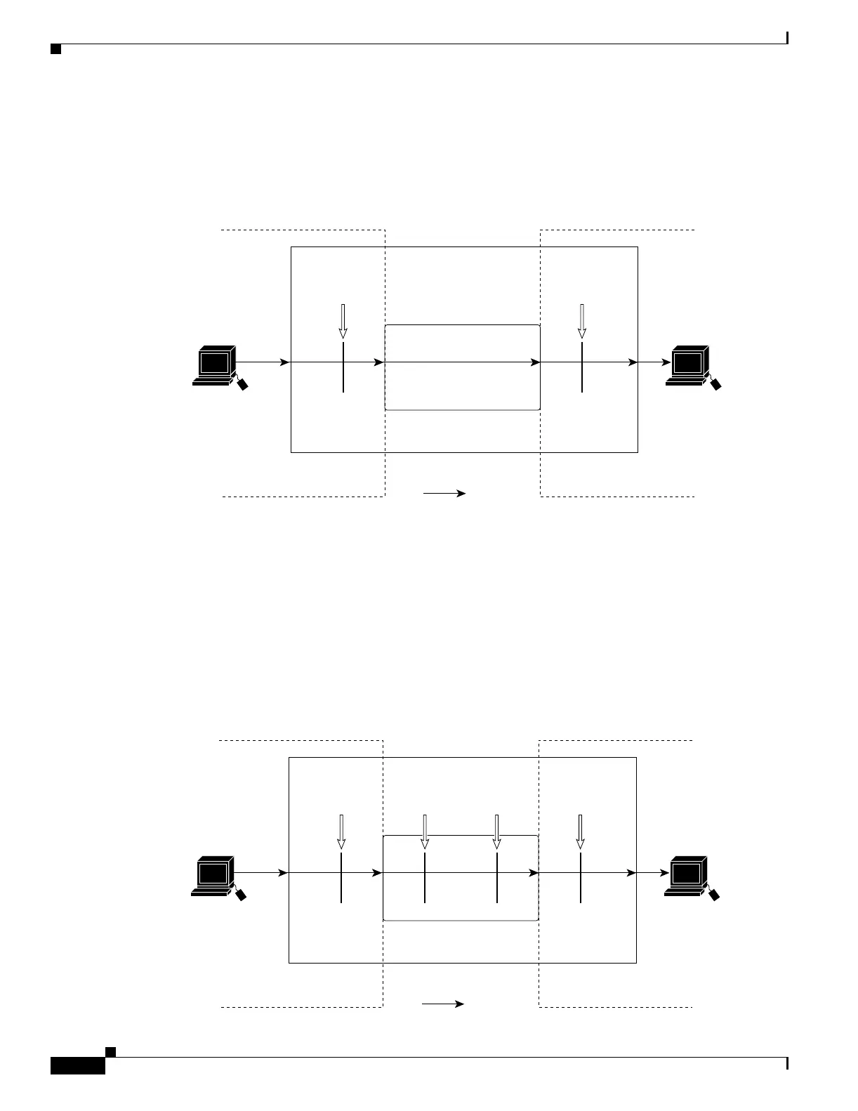
ACLs and Bridged Packets
Figure 25-7 shows how an ACL is applied on fallback-bridged packets. For bridged packets, only
Layer 2 ACLs are applied to the input VLAN. Only non-IPv4, non-ARP packets can be fallback-bridged.
Figure 25-7 Applying ACLs on Bridged Packets
ACLs and Routed Packets
Figure 25-8 shows how ACLs are applied on routed packets. For routed packets, the ACLs are applied
in this order:
1. VLAN map for input VLAN
2. Input router ACL
3. Output router ACL
4. VLAN map for output VLAN
Figure 25-8 Applying ACLs on Routed Packets
Frame
Fallback bridge
VLAN 10
Host A
(VLAN 10)
Packet
101358
VLAN 20
Host B
(VLAN 20)
VLAN 10
map
VLAN 20
map
Frame
Routing function
VLAN 10
Host A
(VLAN 10)
Packet
101359
VLAN 20
Host B
(VLAN 20)
VLAN 10
map
Input
router
ACL
Output
router
ACL
VLAN 20
map