30-11
Catalyst 3750 MetroSwitch Software Configuration Guide
78-15870-01
Chapter 30 Configuring MPLS and EoMPLS
Configuring MPLS VPNs
Configuring Static Route PE-to-CE Routing Sessions
Beginning in privileged EXEC mode, follow these steps on the PE router to configure static routing:
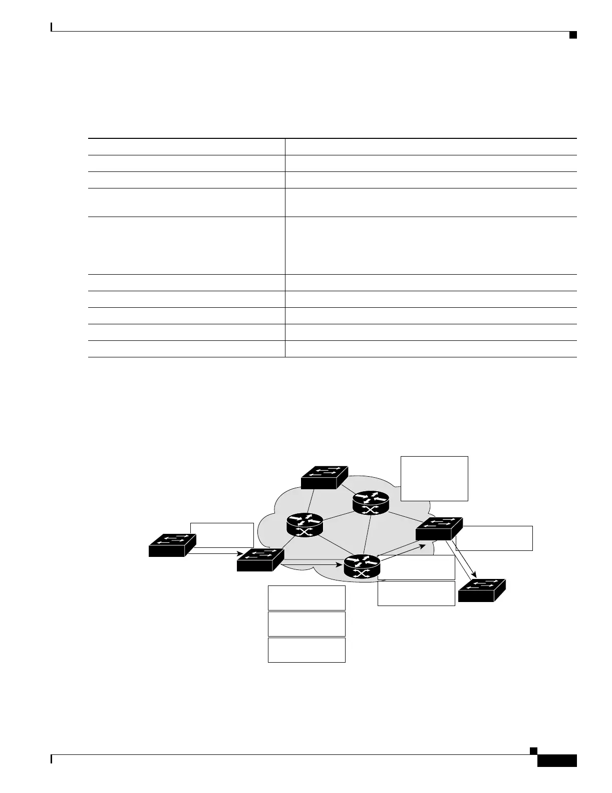
Packet Flow in an MPLS VPN
Figure 30-3 is an example of packet flow between two customer sites in an MPLS VPN network.
Figure 30-3 Sample MPLS VPN Packet Flow
Command Purpose
Step 1
configure terminal Enter global configuration mode.
Step 2
ip route vrf vrf-name prefix mask Define the VRF static routing table to use for PE-to-CE sessions.
Step 3
router bgp autonomous-system-number Enter the BGP routing process AS number, and enter router
configuration mode.
Step 4
address-family ipv4 [unicast] vrf vrf-name Define static route parameters for every PE-to-CE routing session,
and enter VRF address-family configuration mode.
Note The default is off for auto-summary and synchronization in
the VRF address-family configuration mode.
Step 5
redistribute static Redistribute VRF static routes into the VRF BGP table.
Step 6
redistribute connected Redistribute directly connected networks into the VRF BGP table.
Step 7
end Return to privileged EXEC mode.
Step 8
show ip bgp [ipv4] Verify the configuration.
Step 9
copy running-config startup-config (Optional) Save your entries in the configuration file.
101099
IP destination:
16.2.1.1
Label 42
destination: CE2
IP destination:
16.2.1.1
16.2/16
16.1/16
VPN A, site 1
CE1
IP destination:
16.2.1.1
Label N
destination: PE3
Label 42
destination: CE2
IP destination:
16.2.1.1
VPN A, site 2
CE2
PE3
P2P2
Step 1
Step 3
Step 4
PE2
P1
PE1
BGP
VPN-IPv4
Net RD:16.2/16
Next hop:PE3
Label 42
Step 2
P3