33-2
Catalyst 3750 Metro Switch Software Configuration Guide
78-15870-01
Chapter 33 Configuring Fallback Bridging
Configuring Fallback Bridging
The switch creates a VLAN-bridge spanning-tree instance when a bridge group is created. The switch
runs the bridge group and treats the SVIs and routed ports in the bridge group as its spanning-tree ports.
These are the reasons for placing network interfaces into a bridge group:
• To bridge all nonrouted traffic among the network interfaces making up the bridge group. If the
packet destination address is in the bridge table, the packet is forwarded on a single interface in the
bridge group. If the packet destination address is not in the bridge table, the packet is flooded on all
forwarding interfaces in the bridge group. A source MAC address is learned on a bridge group only
when the address is learned on a VLAN (the reverse is not true).
• To participate in the spanning-tree algorithm by receiving, and in some cases sending, BPDUs on
the LANs to which they are attached. A separate spanning-tree process runs for each configured
bridge group. Each bridge group participates in a separate spanning-tree instance. A bridge group
establishes a spanning-tree instance based on the BPDUs it receives on only its member ports. If the
bridge STP BPDU is received on a port whose VLAN does not belong to a bridge group, the BPDU
is flooded on all the forwarding ports of the VLAN.
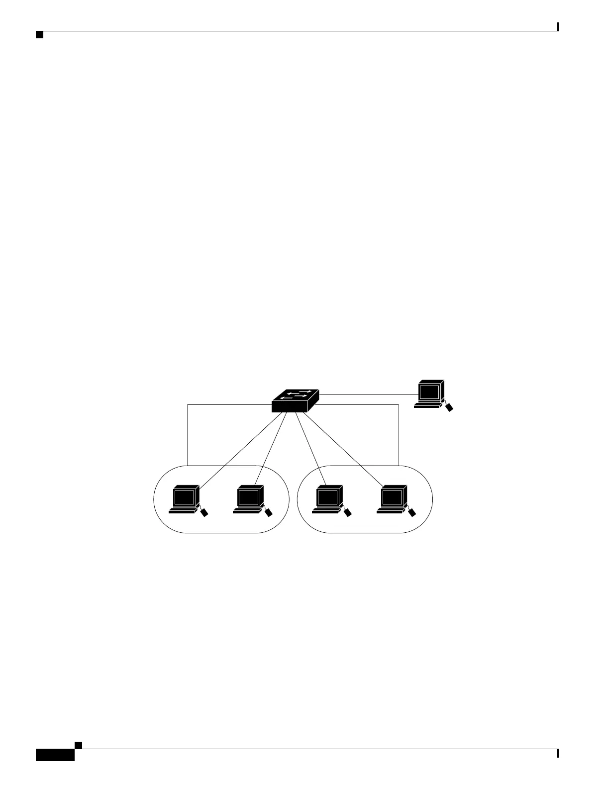
Figure 33-1 shows a fallback bridging network example. The switch has two ports configured as SVIs
with different assigned IP addresses and attached to two different VLANs. Another port is configured as
a routed port with its own IP address. If all three of these ports are assigned to the same bridge group,
non-IP protocol frames can be forwarded among the end stations connected to the switch even though
they are on different networks and in different VLANs. IP addresses do not need to be assigned to routed
ports or SVIs for fallback bridging to work.
Figure 33-1 Fallback Bridging Network Example
Configuring Fallback Bridging
These sections describe how to configure fallback bridging on your switch:
• Default Fallback Bridging Configuration, page 33-3
• Fallback Bridging Configuration Guidelines, page 33-3
• Creating a Bridge Group, page 33-3 (required)
• Adjusting Spanning-Tree Parameters, page 33-5 (optional)
101240
Host A
Host C
SVI 1172.20.128.1 172.20.129.1
Layer 3 switch
Routed port
172.20.130.1
SVI 2
VLAN 20
Host B
VLAN 30