30-13
Catalyst 3750 MetroSwitch Software Configuration Guide
78-15870-01
Chapter 30 Configuring MPLS and EoMPLS
Understanding EoMPLS
The point-to-point VC requires you to configure VC endpoints at the two PE routers. Only the PE routers
at the ingress and egress points of the MPLS backbone know about the VCs dedicated to transporting
Layer 2 traffic. Other routers do not have table entries for these VCs.
This section includes additional information about these topics:
• Interaction with Other Features, page 30-13
• EoMPLS Limitations, page 30-14
Interaction with Other Features
This section describes how EoMPLS interacts other features. It includes these sections:
• EoMPLS and 802.1Q Tunneling, page 30-13
• EoMPLS and Layer 2 Tunneling, page 30-14
• EoMPLS and QoS, page 30-14
EoMPLS and 802.1Q Tunneling
IEEE 802.1Q tunneling enables service providers to use a single VLAN to support customers who have
multiple VLANs, while preserving customer VLAN IDs and segregating traffic in different VLANs. For
more information about 802.1Q tunneling, see Chapter 13, “Configuring IEEE 802.1Q and Layer 2
Protocol Tunneling.”
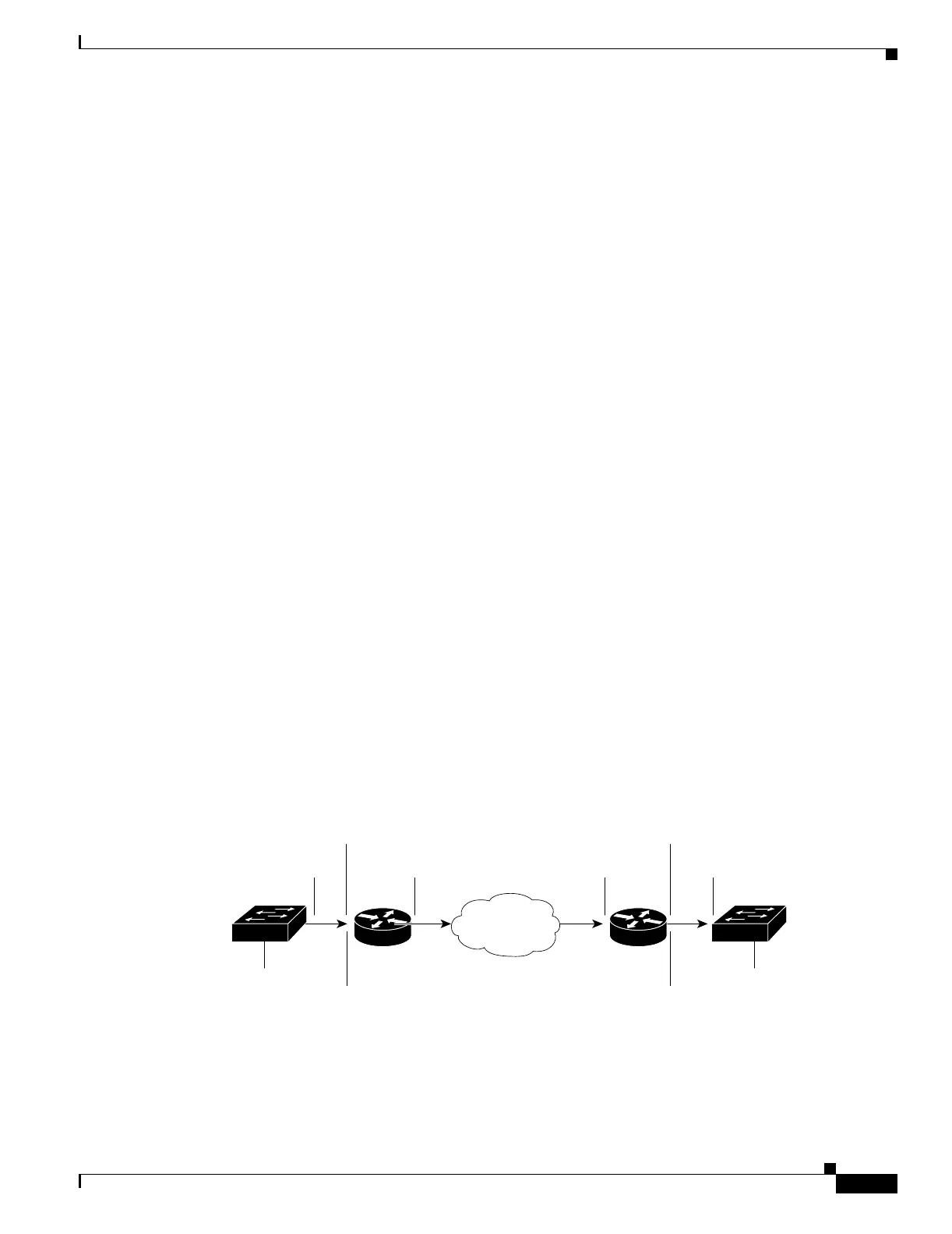
Figure 30-4 is an example configuration where 802.1Q-tunneled traffic is forwarded using EoMPLS
over an MPLS network. To support 802.1Q tunneling in a topology where a Layer 2 device connects to
an MPLS network through a switch functioning as a PE, the ingress LAN port on the PE that receives
the 802.1Q tunnel-encapsulated traffic (PE1) is configured as a tunnel port that accepts VLAN 100
traffic. On PE1, the interface is configured for port-based EoMPLS forwarding, with PE2 as the
destination IP address. When packets from VLANs 10 to 50 arrive from CE1, they are encapsulated in
VLAN 100 and sent to the PE1 egress port that is connected to the MPLS network. At the egress port,
an MPLS tag is added to the frame header before it is mapped to a VC and forwarded to the next MPLS
PE (PE2).
Figure 30-4 EoMPLS Example
VLANs 10-50
(VLAN 100 tag
removed)
CE1 CE2PE1 PE2
101823
MPLS
cloud
VLANs 10-50
VLANs 10-50
encapsulated in
VLAN 100
VLANs 10-50
encapsulated in
VLAN 100
802.1Q
tunnel port
802.1Q
tunnel port
Trunk
port
Trunk
port
MPLS label
applied
MPLS label
removed

 Loading...


