7-8
Cisco CRS-1 Series Carrier Routing System Getting Started Guide
Chapter 7 RP Redundancy and Hardware Administration on Cisco IOS XR Software
Configure Routing Interfaces
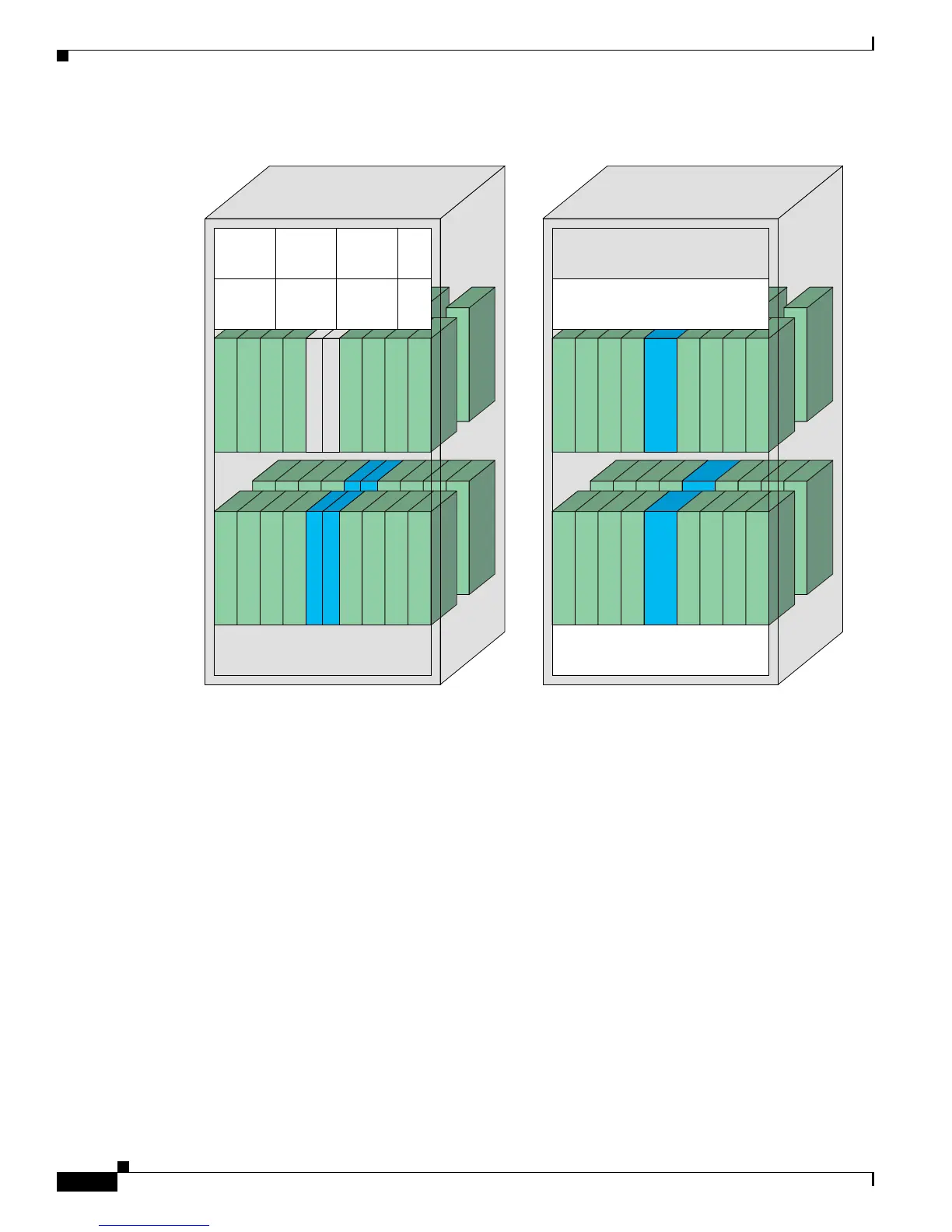
Figure 7-3 MSC and PLIMs in a Single-Chassis System
Every MSC is paired with a PLIM through the midplane of the line card chassis (see Figure 7-4). The
use of separate PLIMs provides the ability to choose a number of interfaces and port densities, such as
OC-192 or OC-48, and allows an MSC to be removed and replaced without having to disturb the cabling
that is connected to the PLIM.
PLIMPLIM
MSC side of chassisPLIM side of chassis
Line card/DRP
15
Line card/DRP
14
Line card/DRP
13
Line card/DRP
12
Line card/DRP
11
Line card/DRP
10
Line card/DRP
9
Line card/DRP
8
MSC (Line card)
7
MSC (Line card)
6
MSC (Line card)
5
MSC (Line card)
4
MSC (Line card)
3 2 1 0
SM0-
SM3
Fabric cards
(FC/S)
SM4-
SM7
Fabric cards
(FC/S)
FT0 (fan tray)
FT1
101403
PLIM
PL8
PLIM
PL9
PLIM
PL
10
PLIM
PL
11
PLIM
PL
12
PLIM
PL
13
PLIM
PL
14
PLIM
PL
15
MSC (Line card)MSC (Line card)
PLIM
PL0
PLIM
PL1
PLIM
PL2
PLIM
PL3
PLIM
PL4
PLIM
PL5
PLIM
PL6
PLIM
PL7
FC0
FC1
A0
B0
A1
B1
A2
B2
AM0
AM1
RP0
RP1
MSC (Line card)
MSC (Line card)
MSC (Line card)
 Loading...


