Chapter 2 Getting Started with CMS
Cluster Manager and VSM
2-6
Catalyst 2900 Series XL and Catalyst 3500 Series XL Software Configuration Guide
78-6511-05
Cluster Tree
The cluster tree appears in the Cluster Manager left frame (Figure 2-2). It displays
a list of the switches in a specific cluster. The sequence of the cluster tree icons
mirrors the sequence of the switch front-panel images. Select a cluster-tree icon
to select the corresponding switch image. After you select a switch, you can
configure switch-wide settings from either the Cluster Manager menu bar options
or the device pop-up menu.
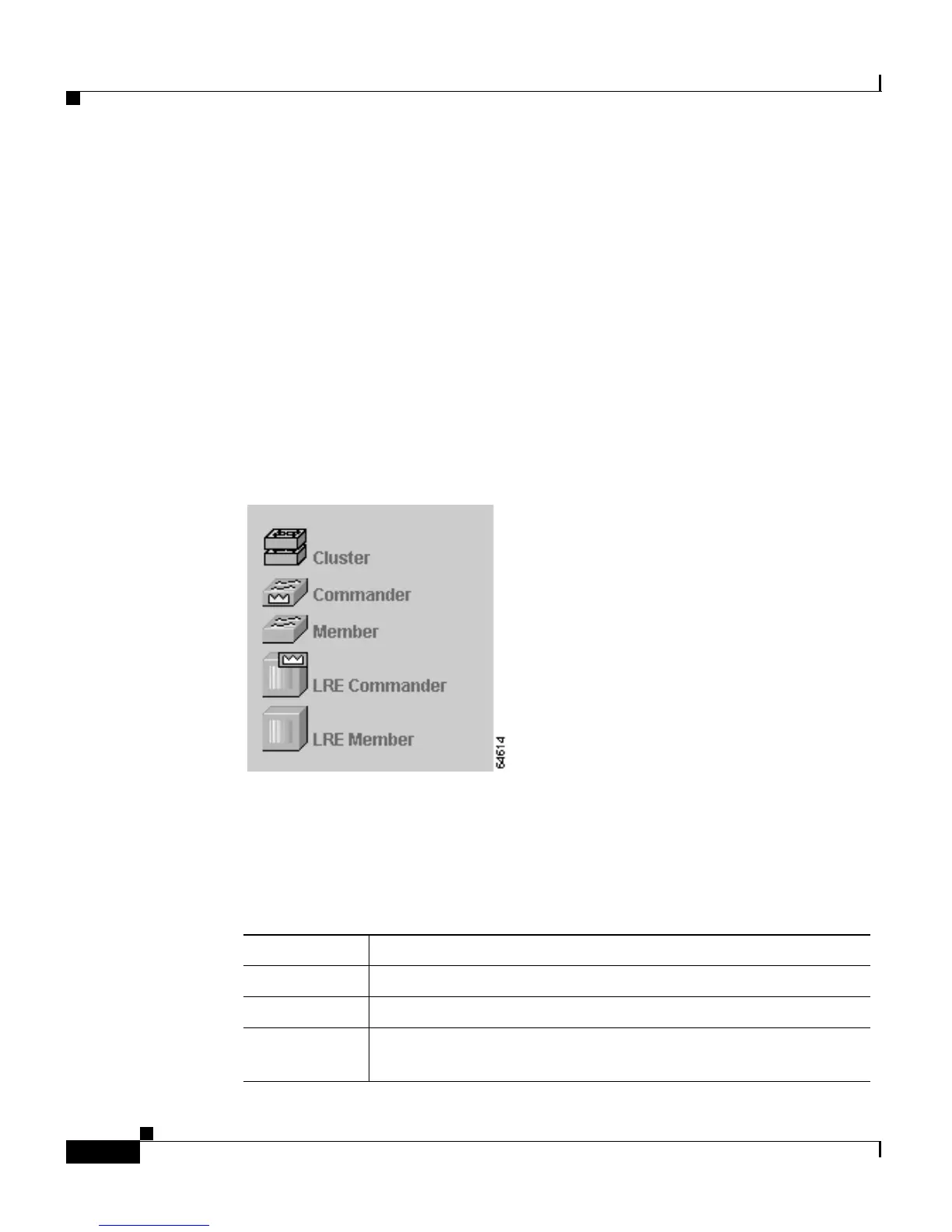
The cluster tree uses a subset of the same icons used in the topology displayed in
Cluster View and Cluster Builder. Figure 2-3 shows the device icons as they
appear in the cluster tree.
Figure 2-3 Cluster Tree Icons
The cluster tree displays the cluster name and the names and the status of cluster
members (Table 2-1). For example, a yellow switch icon in the cluster tree means
that particular switch is overheating or the fan is broken. Complete descriptions
of the icons and icon colors are available by selecting Help > Legend.
Table 2-1 Cluster Tree Icon Colors
Color Switch Status
Green Switch is operating normally.
Yellow A system fault exists, such as the internal fan is not operating.
Red Switch is not powered up, has lost power, or the command
switch is unable to communicate with the member switch.