2-7
Catalyst 2900 Series XL and Catalyst 3500 Series XL Software Configuration Guide
78-6511-05
Chapter 2 Getting Started with CMS
Cluster Manager and VSM
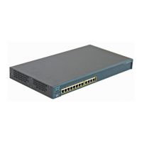
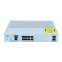
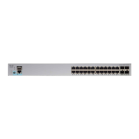
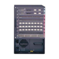
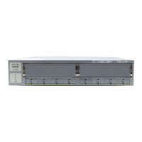
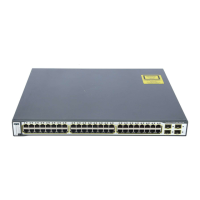
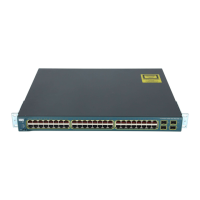
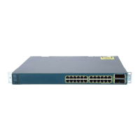
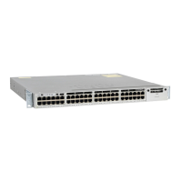
Switch Images
Use the front-panel images for visual switch management from a remote station.
The LEDs on these images are updated at user-configurable polling intervals,
making them as useful as the LEDs on the actual switches themselves. To change
the polling intervals, select System > User Settings from VSM or Cluster > User
Settings from Cluster Manager.
The following sections provide complete descriptions of the Catalyst 2900 XL
and Catalyst 3500 XL LED images:
• System LED
• RPS LED
• Port LEDs
Summarized descriptions of the LED images are available from the VSM and
Cluster Manager menu bar by choosing Help > Legend.
System LED
The system LED shows whether the switch is receiving power and functioning
properly. Table 2-2 lists the LED colors and their meanings.
Table 2-2 System LED
Color System Status
Black (off) System is not powered up.
Green System is operating normally.
Amber System is receiving power but is not functioning properly.
 Loading...
