ED 15062-7 • MICROTECH II CHILLER CONTROLLER 12 www.DaikinApplied.com
basIC ProToCol InformaTIon
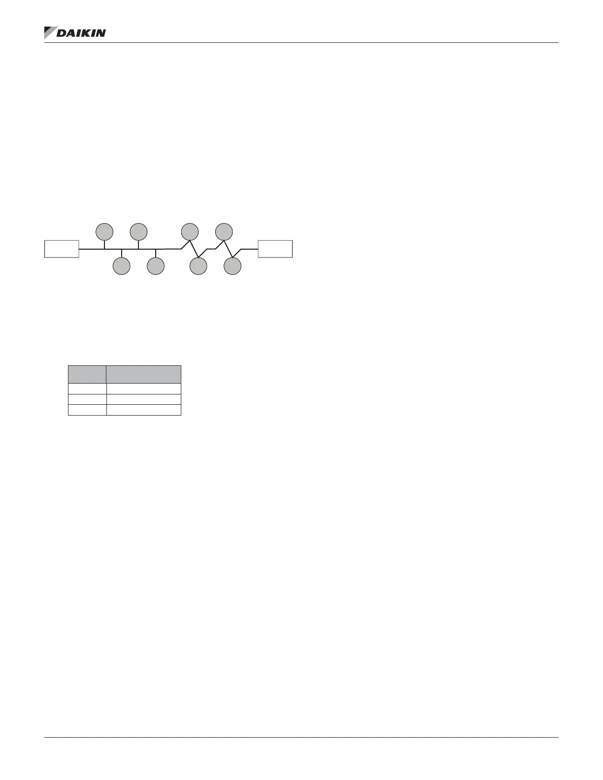
Doubly Terminated Networks
You can extend the maximum total cable length without using
a repeater by using doubly-terminated network topology. The
trade-offs are (1) this network topology must be rigorously
followed during the installation and subsequent retrots and
(2) two terminations must be installed at the ends of the
bus for proper transmission performance. Refer to Echelon
LONWORKS FTT-10A Transceiver User’s Guide (see
Reference Documents section for details.)
NOTE: Limitations to wire lengths apply and must be
observed.
Figure 3: Doubly Terminated Network Topology
Doubly Terminated Topology Restrictions
The restrictions on doubly-terminated bus topology are as
follows:
1. The maximum number of nodes per segment is 64.
2. The maximum total bus length depends on the wire size:
Wire Size
Maximum Cable
Length
24 AWG 2952 ft (900 m)
22 AWG 4590 ft (1400 m)
16 AWG 8855 ft (2700 m)
3. The maximum stub length is 9.8 ft (3 m).
A stub is a piece of cable that is wired between the
node and the bus (see Figure 1). Note that if the bus is
wired directly to the node, there is no stub, and thus the
stub length is zero. If you are wiring to a eld terminal
strip on a unit, be sure to account for any factory wiring
between the terminal strip and the controller. This wiring
is considered part of the stub.
4. Two terminations are required in each segment. One
must be located at each end of the bus.
Network Cable Termination
LONWORKS network segments require termination for proper
data transmission performance. The type and number of
terminations depend on network topology. Refer to Echelon
LONWORKS FTT-10A Transceiver User’s Guide (see
Reference Documents section for details.)
LONWORKS Network Addressing
Every Neuron
®
Chip has a unique 48-bit Neuron ID or
physical address. This address is generally used only at initial
installation or for diagnostic purposes. For normal network
operation, a device address is used.
Device addresses are dened at the time of network
conguration. All device addresses have three parts. The
rst part is the Domain ID, designating the domain. Devices
must be in the same domain in order to communicate with
each other. The second part is the Subnet ID that species a
collection of up to 127 devices that are on a single channel or
a set of channels connected by repeaters. There may be up
to 255 subnets in a domain. The third part is the Node ID that
identies an individual device within the subnet.
A group is a logical collection of devices within a domain.
Groups are assembled with regard for their physical location
in the domain. There may be up to 256 groups in a domain. A
group address is the address that identies all devices of the
group. There may be any number of devices in a group when
unacknowledged messaging is used. Groups are limited to 64
devices if acknowledged messaging is used.
A broadcast address identies all devices within a subnet or
domain.
Commissioning the Network
Pressing the service pin, switch on the LONWORKS
Communication Module, generates a service pin message,
which contains the Neuron ID and the program code
identication of the node. A service pin message is a network
message that is generated by a node and broadcast on the
network. It can be used to commission the LONWORKS
network.
A network conguration tool maps device Neuron IDs to
the domain/subnet/node logical addressing scheme when it
creates the network image, the logical network addresses and
connection information for all devices (nodes) on the network.
External Interface File (XIF)
LONMARK guidelines specify exact documentation rules
so that proprietary conguration tools are not required
to commission and congure LONWORKS devices. The
LONWORKS Chiller Communication Module is self-
documenting so that any network management tool can obtain
all the information needed over the network to connect it
into the system and to congure and manage it. An external
interface le (a specially formatted PC text le with an
extension .XIF) is available so that any network tool can design
and congure it prior to installation. For a copy of the XIF le
contact your local Daikin Applied representative.
Termination Termination