basIC ProToCol InformaTIon
www.DaikinApplied.com 11 ED 15062-7 • MICROTECH II CHILLER CONTROLLER
Network Considerations
Network Topology
Each LONWORKS Communication Module is equipped
with an FTT-10A transceiver for network communication.
This transceiver allows for (1) free topology network wiring
schemes using twisted pair (unshielded) cable and (2) polarity
insensitive connections at each node. These features greatly
simplify installation and reduce network commissioning
problems. Additional nodes may be added with little regard to
existing cable routing.
Free Topology Networks
A LONWORKS “free topology network” means that devices
(nodes) can be connected to the network in a variety of
geometric congurations. For example, devices can be
daisy-chained from one device to the next, connected with
stub cables branching off from a main cable, connected
using a tree or star topology, or any of these congurations
can be mixed on the same network as shown in Figure
1. Free topology segments require termination for proper
transmission performance. Only one termination is required.
It may be placed anywhere along the segment. Refer to
Echelon LONWORKS FTT-10A Transceiver User’s Guide (see
Reference Documents section details.)
Free topology networks may take on the following topologies:
• Bus
• Ring
• Star
• Mixed - Any combination of Bus, Ring, and Star
NOTE: Limitations to wire lengths apply and must be
observed.
Figure 1: Singly Terminated Free Topology
A network segment is any part of the free topology network in
which each conductor is electrically continuous. Each of the
four diagrams in is a illustration of a network segment. Some
applications may require two or more segments. See Free
Topology Restrictions. If necessary, segments can be joined
with FTT-10A-to-FTT-10A physical layer repeaters. See Figure
2. Refer to Echelon LONWORKS FTT-10A Transceiver User’s
Guide (see Reference Documents section for details.)
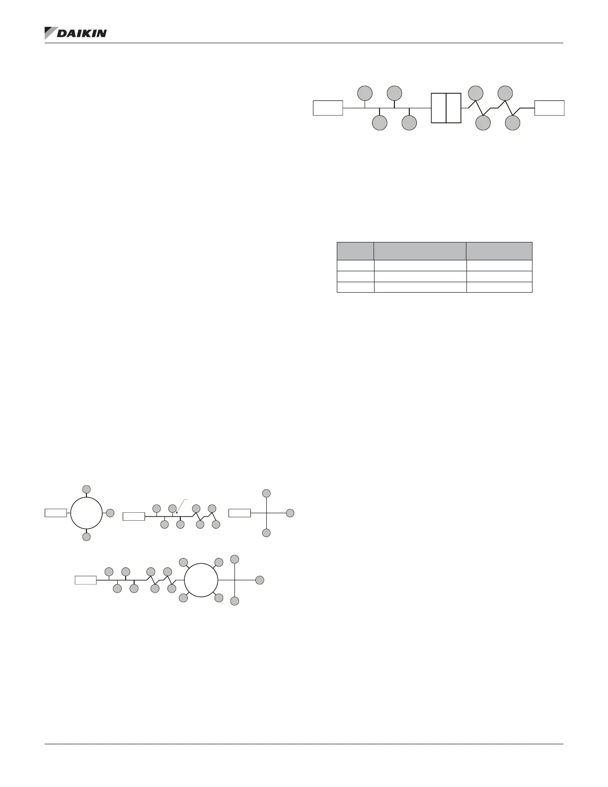
Figure 2: Combining Network Segments with a Repeater
Free Topology Restrictions
Although free topology wiring is very exible, there are
restrictions. A summary follows, refer to the Echelon FTT-10A
User’s Guide for details (see Reference Documents section for
details.)
1. The maximum number of nodes per segment is 64.
2. The maximum total bus length depends on the wire size:
Wire Size
Maximum Node-to-Node
Length
Maximum Cable
Length
24 AWG 820 ft (250 m) 1476 ft (450 m)
22 AWG 1312 ft (400 m) 1640 ft (500 m)
16 AWG 1640 ft (500 m) 1640 ft (500 m)
The longest cable path between any possible pair of
nodes on a segment must not exceed the maximum
node-to-node distance. If two or more paths exist
between a pair of nodes (e.g., a loop topology), the
longest path should be considered. Note that in a bus
topology, the longest node-to-node distance is equal
to the total cable length. The total length of all cable in
a segment must not exceed the maximum total cable
length.
3. One termination is required in each segment. It may be
located anywhere along the segment.
Termination
Star Topology
Termination
Ring Topology
Termination
Singly Terminated Bus Topology
Stub
}
Termination
Mixed Topology
Termination Termination
FTT-10A
FTT-10A

 Loading...


