In the Main Menu mode, the parameters are divided into groups. The first digit of the parameter number (from the left) indicates the
parameter group number. The parameter group is then broken down into sub groups, if necessary. For example:
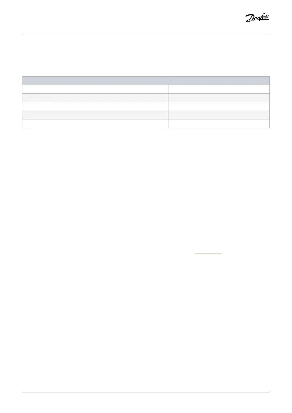
Table 48: Example of Parameter Group Hierarchy
Example Description
0–** Operation/Display Parameter group
0–0* Basic Settings Parameter sub group
Parameter 0-01 Language Parameter
Parameter 0-02 Motor Speed Unit Parameter
Parameter 0-03 Regional Settings Parameter
7.2.2 Parameter Navigation
Use the following LCP keys to navigate through the parameters.
• Press [▲] [▼] to scroll up or down.
• Press [◄] [►] to shift a space to the left or right of a decimal point while editing a decimal parameter value.
• Press [OK] to accept the change.
• Press [Cancel] to disregard the change and exit edit mode.
• Press [Back] twice to show the status view.
• Press [Main Menu] once to go back to the main menu.
7.2.3 Programming Example for an Open-loop Application
Context:
This procedure, which is used to configure a typical open-loop application, programs the drive to receive a 0–10 V DC analog control
signal on input terminal 53. The drive responds by providing 20–50 Hz output to the motor proportional to the input signal (0–10 V
DC=20–50 Hz). The wiring connections used to enable the external device set-up are shown in illustration 59.
Commissioning
Operating Guide | VLT® AQUA Drive FC 202
AQ262141056213en-000101 / 130R0882
102 | Danfoss A/S © 2018.10

 Loading...


