8 Wiring Configuration Examples
8.1 Application Examples
The examples in this section are intended as a quick reference for common applications.
• Parameter settings are the regional default values selected in parameter 0-03 Regional Settings, unless otherwise indicated.
• Parameters associated with the terminals and their settings are shown next to the drawings.
• Required switch settings for analog terminals A53 or A54 are also shown.
8.1.1 Wiring Configuration for Automatic Motor Adaptation (AMA)
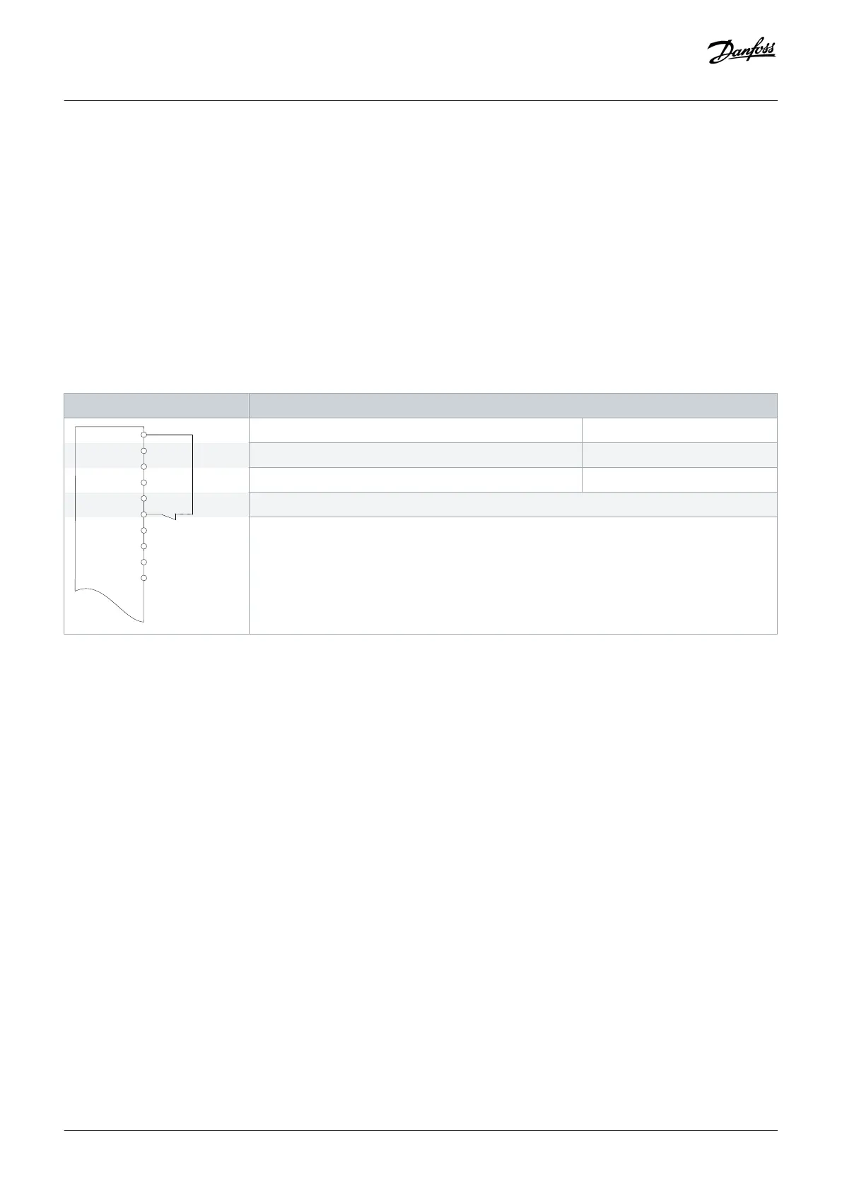
Table 49: Wiring Configuration for AMA with T27 Connected
Parameters
+24 V
+24 V
D IN
D IN
D IN
COM
D IN
D IN
D IN
D IN
e30bu099.10
Function Setting
Parameter 1-29 Automatic Motor Adaptation (AMA) [1] Enable complete AMA
Parameter 5-12 Terminal 27 Digital Input [2]* Coast inverse
*=Default value
Notes/comments:
Set parameter group 1-2* Motor Data according to motor nameplate.
Terminal 27 in the parameter title corresponds to terminal XD2.14 in the control compartment.
Wiring Configuration Examples
Operating Guide | VLT® AQUA Drive FC 202
AQ262141056213en-000101 / 130R0882 | 109
Danfoss A/S © 2018.10

 Loading...


