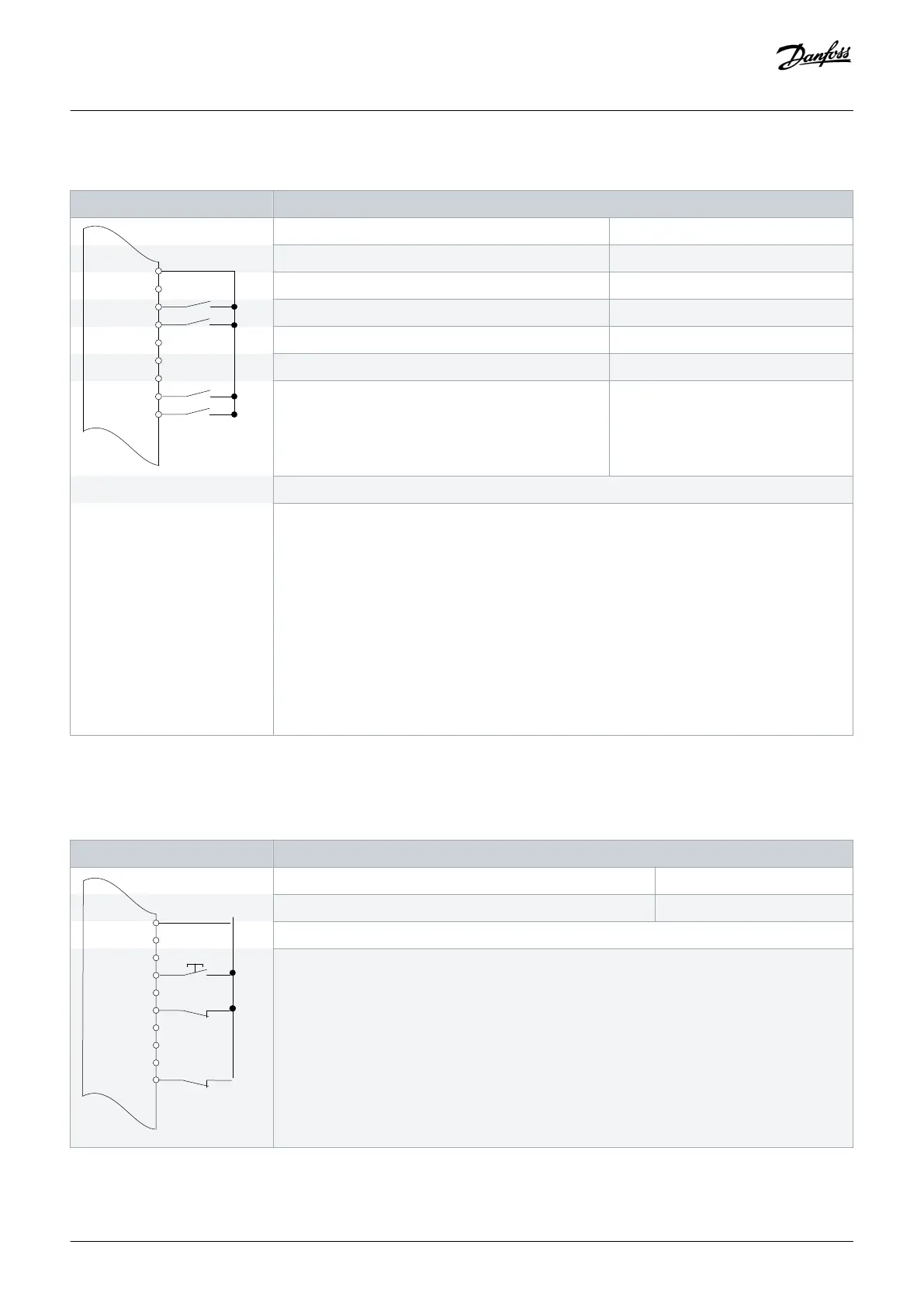
Table 63: Wiring Configuration for Start/Stop with Reversing and 4 Preset Speeds
Parameters
D IN
D IN
COM
D IN
D IN
D IN
e30bu086.10
XD2.13
XD2.18
XD2.14
XD2.15
XD2.16
XD2.17
Function Setting
Parameter 5-10 Terminal 18 Digital Input [8] Start
Parameter 5-11 Terminal 19 Digital Input [10] Reversing*
Parameter 5-12 Terminal 27 Digital Input [0] No operation
Parameter 5-14 Terminal 32 Digital Input [16] Preset ref bit 0
Parameter 5-15 Terminal 33 Digital Input [17] Preset ref bit 1
Parameter 3-10 Preset Reference • Preset ref. 0 = 25%
• Preset ref. 1 = 50%
• Preset ref. 2 = 75%
• Preset ref. 3 = 100%
*=Default value
Notes/comments:
D IN 37 is an option.
Terminal 18 in the parameter title corresponds to terminal XD2.12 in the control compartment.
Terminal 19 in the parameter title corresponds to terminal XD2.13 in the control compartment.
Terminal 27 in the parameter title corresponds to terminal XD2.14 in the control compartment.
Terminal 32 in the parameter title corresponds to terminal XD2.16 in the control compartment.
Terminal 33 in the parameter title corresponds to terminal XD2.17 in the control compartment.
8.1.7 Wiring Configuration: External Alarm Reset
Table 64: Wiring Configuration for External Alarm Reset
Parameter
+24 V
D IN
D IN
D IN
COM
D IN
D IN
D IN
D IN
e30bu088.10
XD2.13
XD2.18
XD2.14
XD2.15
XD2.16
XD2.17
XD2.19
Function Setting
Parameter 5-11 Terminal 19 Digital Input [1] Reset
*=Default value
Notes/comments:
D IN 37 is an option.
Terminal 19 in the parameter title corresponds to terminal XD2.13 in the control compartment.
Wiring Configuration Examples
Operating Guide | VLT® AQUA Drive FC 202
AQ262141056213en-000101 / 130R0882 | 119
Danfoss A/S © 2018.10

 Loading...


