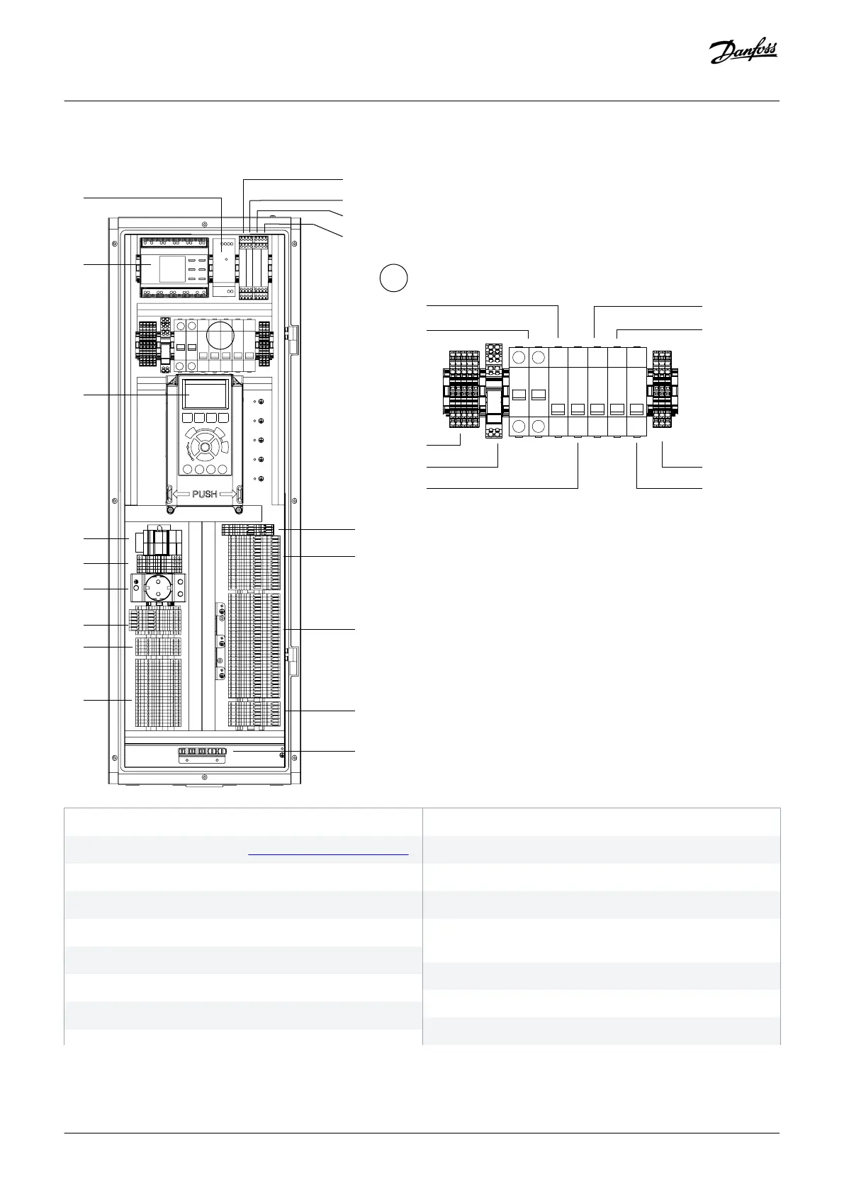
5.7.2 Control Compartment Interior View
1 24 V DC supply (-TB7)
3 Local control panel (LCP). See 3.6.3 Local Control Panel (LCP).
5 Protection terminal block set (-XD11)
7 Contactor control circuit terminal block (-XD0)
9 Customer terminal block/option C0 terminal block (-XDW)
11 Thermal trip indicator relay, output filter cabinet (-KFJ.2)
13 PHF capacitor connect/disconnect contactor relay (-QAF)
15 AC circuit protection MCB (-FC6)
2 Insulation monitor (-BE1)
4 RJ45 terminal blocks 1 and 2 (-RJ45_1 and RJ45_2)
6 Socket outlet (-XD10)
8 Cabinet heater terminal block (-XD4)
10 Thermal trip indicator relay, input power options cabinet (-
KFJ.1)
12 Thermal trip indicator relay, input filter cabinet (-KFJ.3)
14 +24 DC supply protection MCB (-FC7)
16 AC distribution circuit terminal block (-XD1)
Electrical Installation
Operating Guide | VLT® AQUA Drive FC 202
AQ262141056213en-000101 / 130R0882 | 67
Danfoss A/S © 2018.10

 Loading...


