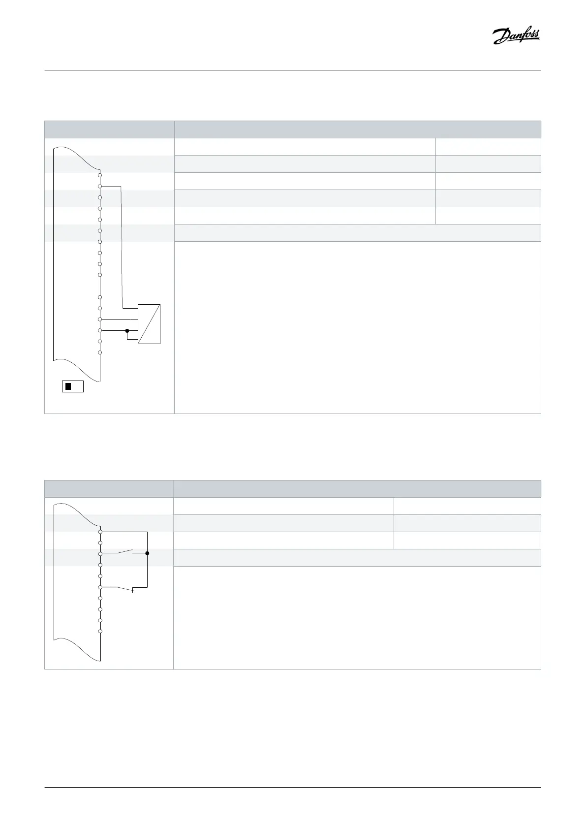
Table 57: Wiring Configuration for Analog Voltage Feedback Transducer (4-wire)
Parameters
+24 V
+24 V
D IN
D IN
D IN
COM
D IN
D IN
D IN
D IN
+10
0-10 V
+
-
e30bu080.10
XD2.10
XD2.11
XD2.12
XD2.15
XD2.16
XD2.17
XD2.19
XD2.6
Function Setting
Parameter 6-20 Terminal 54 Low Voltage 0.07 V*
Parameter 6-21 Terminal 54 High Voltage 10 V*
Parameter 6-24 Terminal 54 Low Ref./Feedb. value 0*
Parameter 6-25 Terminal 54 High Ref./Feedb. Value 50*
*=Default value
Notes/comments:
D IN 37 is an option.
Terminal 54 in the parameter title corresponds to terminal XD2.8 in the control compartment.
8.1.5 Wiring Configuration: Run/Stop
Table 58: Wiring Configuration for Run/Stop Command with External Interlock
Parameter
D IN
D IN
D IN
COM
D IN
D IN
D IN
D IN
Function Setting
Parameter 5-10 Terminal 18 Digital Input [8] Start*
Parameter 5-12 Terminal 27 Digital Input [7] External interlock
*=Default value
Notes/comments:
D IN 37 is an option.
Terminal 18 in the parameter title corresponds to terminal XD2.12 in the control compartment.
Terminal 27 in the parameter title corresponds to terminal XD2.14 in the control compartment.
Wiring Configuration Examples
Operating Guide | VLT® AQUA Drive FC 202
AQ262141056213en-000101 / 130R0882 | 115
Danfoss A/S © 2018.10

 Loading...


