8.1.4 Wiring Configuration: Feedback
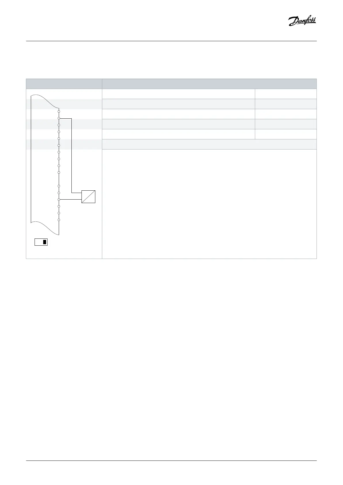
Table 55: Wiring Configuration for Analog Current Feedback Transducer (2-wire)
Parameters
D IN
D IN
+10 V
A IN
A IN
COM
A OUT
COM
Function Setting
Parameter 6-22 Terminal 54 Low Current 4 mA*
Parameter 6-23 Terminal 54 High Current 20 mA*
Parameter 6-24 Terminal 54 Low Ref./Feedb. value 0*
Parameter 6-25 Terminal 54 High Ref./Feedb. Value 50*
*=Default value
Notes/comments:
D IN 37 is an option.
Terminal 54 in the parameter title corresponds to terminal XD2.8 in the control compartment.
Wiring Configuration Examples
Operating Guide | VLT® AQUA Drive FC 202
AQ262141056213en-000101 / 130R0882 | 113
Danfoss A/S © 2018.10

 Loading...


