8.1.11 Wiring Configuration for a Relay Set-up with Smart Logic Control
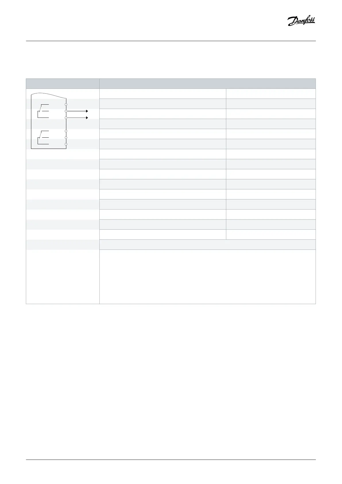
Table 68: Wiring Configuration for a Relay Set-up with Smart Logic Control
Parameters
XD2.22
XD2.23
XD2.24
XD2.25
XD2.26
Function Setting
Parameter 4-30 Motor Feedback Loss Function [1] Warning
Parameter 4-31 Motor Feedback Speed Error 100 RPM
Parameter 4-32 Motor Feedback Loss Timeout 5 s
Parameter 7-00 Speed PID Feedback Source [2] MCB 102
Parameter 17-11 Resolution (PPR) 1024*
Parameter 13-00 SL Controller Mode [1] On
Parameter 13-01 Start Event [19] Warning
Parameter 13-02 Stop Event [44] Reset key
Parameter 13-10 Comparator Operand [21] Warning no.
Parameter 13-11 Comparator Operator [1] ≈ (equal)*
Parameter 13-12 Comparator Value 90
Parameter 13-51 SL Controller Event [22] Comparator 0
Parameter 13-52 SL Controller Action [32] Set digital out A low
Parameter 5-40 Function Relay [80] SL digital output A
*=Default value
Notes/comments:
If the limit in the feedback monitor is exceeded, warning 90, Feedback Mon. is issued. The SLC
monitors warning 90, Feedback Mon. and if the warning becomes true, relay 1 is triggered. Exter-
nal equipment may require service.
However, if the feedback error goes below the limit again within 5 s and the warning disappears,
press [Reset] on the LCP.
8.1.12 Wiring Configuration for a Submersible Pump
The system consists of a submersible pump controlled by a Danfoss VLT
®
AQUA Drive and a pressure transmitter. The transmitter gives
a 4–20 mA feedback signal to the drive, which keeps a constant pressure by controlling the speed of the pump. To design a drive for a
submersible pump application, there are a few important issues to consider. Select the drive according to motor current.
Wiring Configuration Examples
Operating Guide | VLT® AQUA Drive FC 202
AQ262141056213en-000101 / 130R0882
122 | Danfoss A/S © 2018.10

 Loading...


