3.6.3 Local Control Panel (LCP)
e30bf155.10
Auto
On
Reset
Hand
On
Off
A3
B1
B2
B4
B3
C1
C2
C3
C4
C5
D1
D2
D3
E1
E2
E3
E4
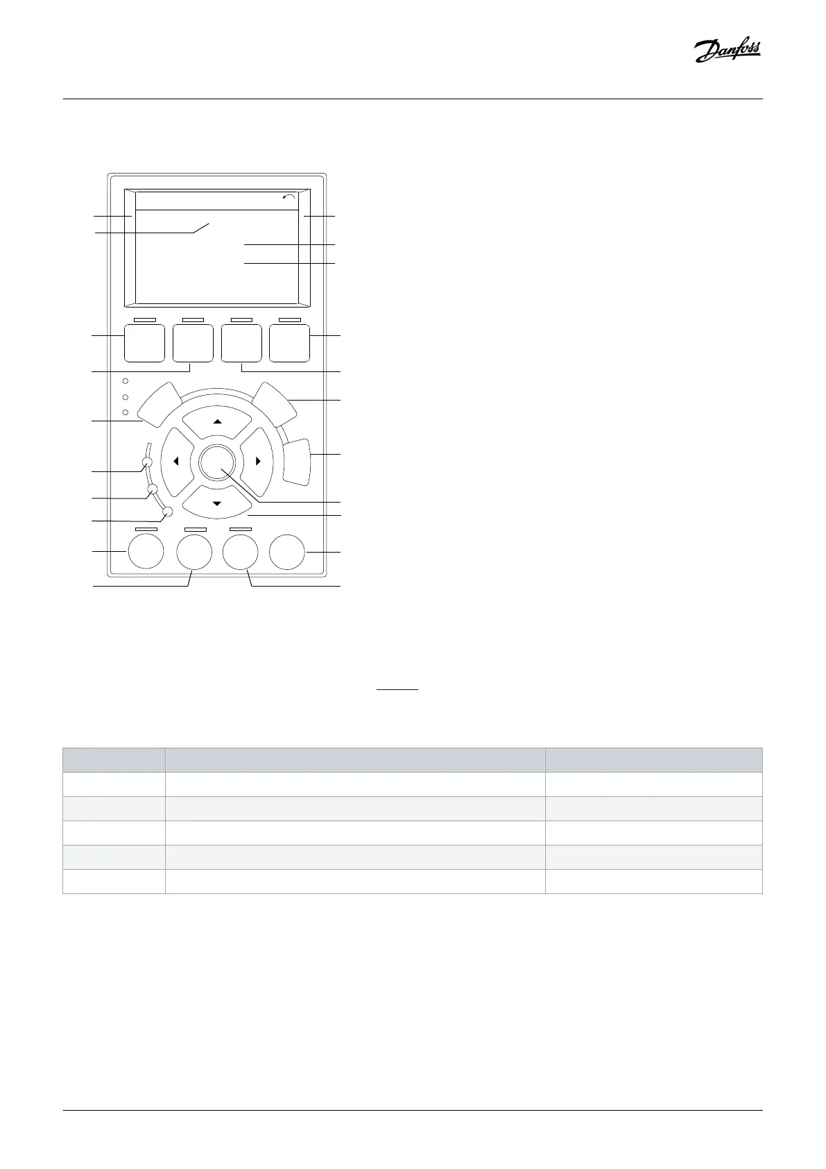
Illustration 9: Graphical Local Control Panel (LCP)
A. Display area
Each display readout has a parameter associated with it. See table 15. The information shown on the LCP can be customized for
specific applications. Refer to My Personal Menu in the LCP Menu section.
Table 15: LCP Display Area
Callout Parameter Default setting
A1.1 Parameter 0-20 Display Line 1.1 Small Reference [Unit]
A1.2 Parameter 0-21 Display Line 1.2 Small Analog input 53 [V]
A1.3 Parameter 0-22 Display Line 1.3 Small Motor current [A]
A2 Parameter 0-23 Display Line 2 Large Frequency [Hz]
A3 Parameter 0-24 Display Line 3 Large Feedback [Unit]
B. Menu keys
Menu keys are used to access the menu for setting up parameters, toggling through status display modes during normal operation,
and viewing fault log data.
Product Overview
Operating Guide | VLT® AQUA Drive FC 202
AQ262141056213en-000101 / 130R0882 | 27
Danfoss A/S © 2018.10

 Loading...


