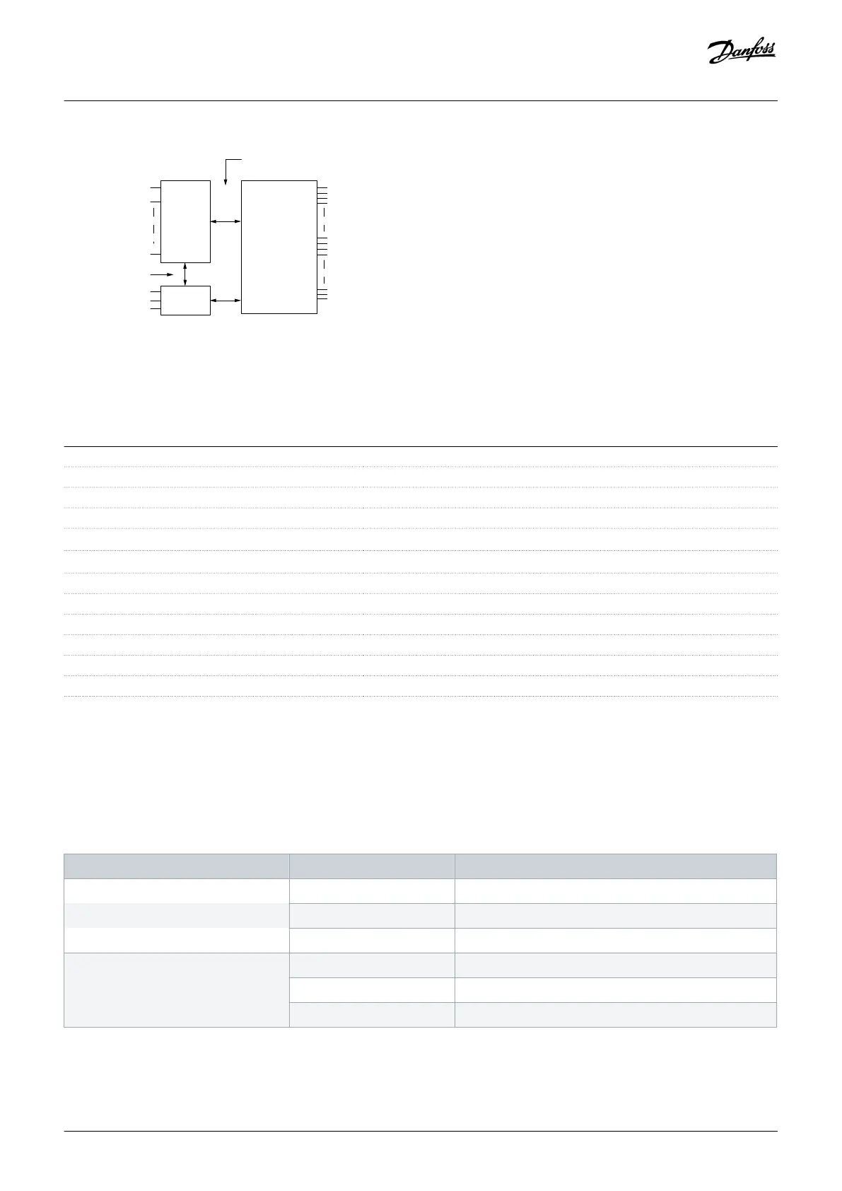
Functional
isolation
PELV isolation
Motor
DC-bus
High
voltage
+24 V
RS485
18
37
e30ba117.11
Illustration 71: PELV Isolation
10.7 Filter Specifications
10.7.1 Passive Harmonic Filter Specifications
Phase imbalance Maximum of 3% (Drives have to be functional up to 8%)
Voltage variation +10%–15%
Nominal frequency -2%, +2% (of 50 Hz or 60 Hz) when PHF is installed
Overload capability 150% for 60 s in a period of 10 minutes
Maximum inrush current, drive side Maximum 5xI
nom drive
Maximum inrush current, PHF input side Maximum 2xI
nom drive
Cos of IL at 25% IPHF, N 0.85 Ind
Cos of IL at 50% IPHF, N 0.88 Ind
Cos of IL at 75% IPHF, N 0.92 Ind
Cos of IL at 100% IPHF, N 0.99 Ind
Cos of IL at 160% IPHF, N 0.98 Ind
Power derating Same as drive
10.7.2 Line Reactor Specifications
All line reactors are equipped with thermal switches and are looped to the enclosed drive for overtemperature protection. For more
details, refer to the control compartment section. The line reactor configuration varies depending on the enclosure and voltage
required.
Table 86: Line Reactor Configuration for D9h–D10h and E5h–E6h Enclosures, 380–480 V
Enclosure Model Line reactor [A]
D9h N110 312
N132 312
N160 425
D10h N200 425
N250 2x312
N315 2x312
Specifications
Operating Guide | VLT® AQUA Drive FC 202
AQ262141056213en-000101 / 130R0882
176 | Danfoss A/S © 2018.10

 Loading...


