Table 54: Wiring Configuration for Speed Up/Down
Parameter
+24 V
+24 V
D IN
D IN
D IN
COM
D IN
D IN
D IN
D IN
e30bu076.10
XD2.10
Function Setting
Parameter 5-10 Terminal 18 Digital Input [8] Start*
Parameter 5-12 Terminal 27 Digital Input [19] Freeze Reference
Parameter 5-13 Terminal 29 Digital Input [21] Speed Up
Parameter 5-14 Terminal 32 Digital Input [22] Speed Down
*=Deafult value
Notes/comments:
D IN 37 is an option.
Terminal 18 in the parameter title corresponds to terminal XD2.12 in the control compartment.
Terminal 27 in the parameter title corresponds to terminal XD2.14 in the control compartment.
Terminal 29 in the parameter title corresponds to terminal XD2.15 in the control compartment.
Terminal 32 in the parameter title corresponds to terminal XD2.16 in the control compartment.
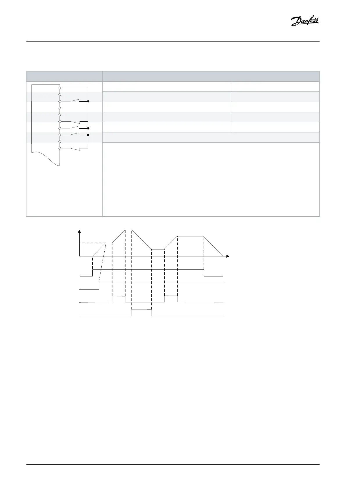
Reference
Start (XD2.12)
Freeze ref (XD2.14)
Speed up (XD2.15)
Speed down (XD2.16)
Illustration 60: Speed Up/Down
Wiring Configuration Examples
Operating Guide | VLT® AQUA Drive FC 202
AQ262141056213en-000101 / 130R0882
112 | Danfoss A/S © 2018.10

 Loading...


