Table 52: Wiring Configuration for Analog Speed Reference (Current)
Parameters
Function Setting
Parameter 6-12 Terminal 53 Low Current 4 mA*
Parameter 6-13 Terminal 53 High Current 20 mA*
Parameter 6-14 Terminal 53 Low Ref./Feedb. value 0 Hz
Parameter 6-15 Terminal 53 High Ref./Feedb. Value 50 Hz
*=Default value
Notes/comments:
D IN 37 is an option.
Terminal 53 in the parameter title corresponds to terminal XD2.7 in the control compartment.
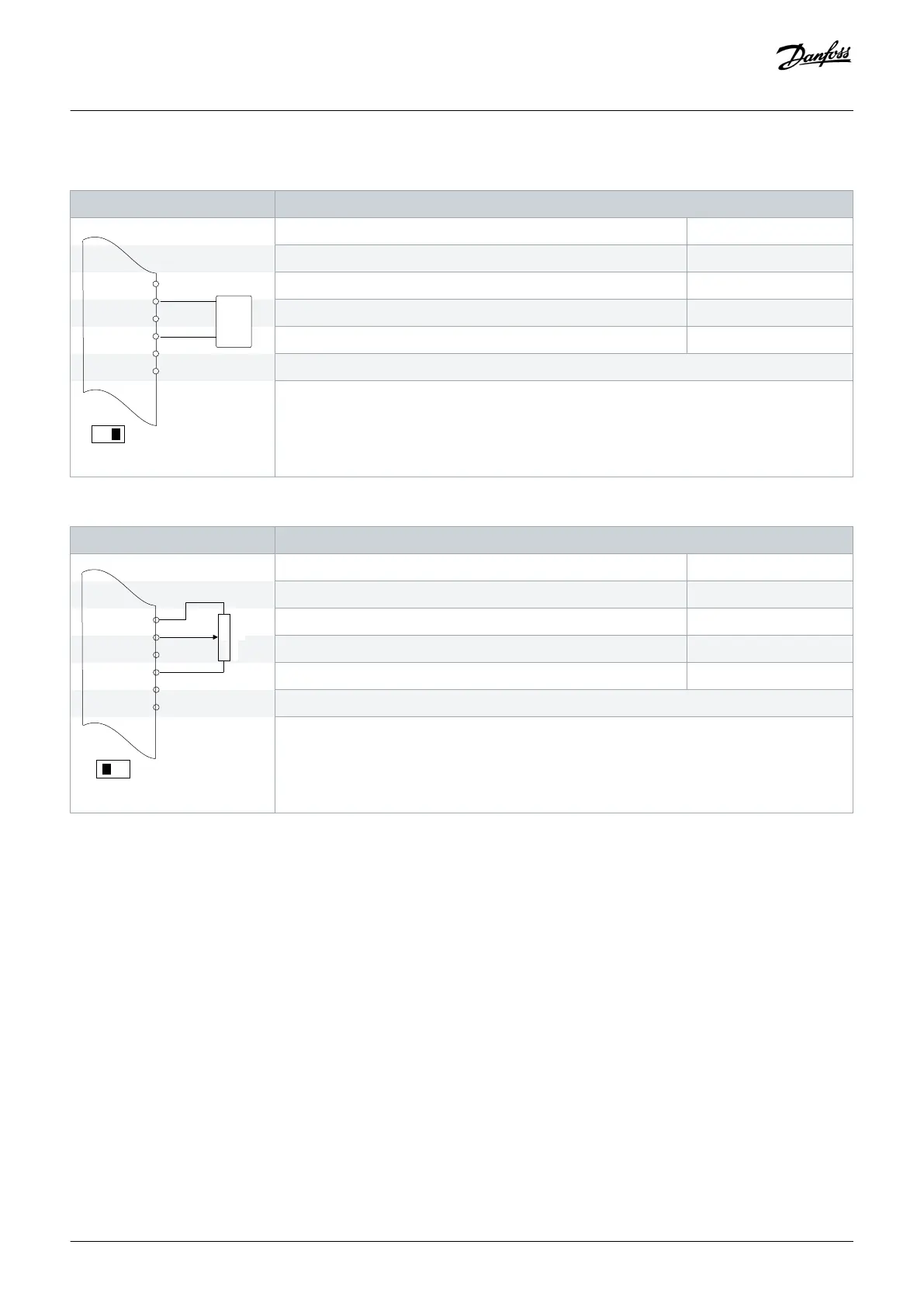
Table 53: Wiring Configuration for Speed Reference (Using a Manual Potentiometer)
Parameters
COM
A OUT
COM
A53
U - I
# 5k#
e30bu075.10
XD2.6
XD2.7
Function Setting
Parameter 6-10 Terminal 53 Low Voltage 0.07 V*
Parameter 6-11 Terminal 53 High Voltage 10 V*
Parameter 6-14 Terminal 53 Low Ref./Feedb. value 0 Hz
Parameter 6-15 Terminal 53 High Ref./Feedb. Value 50 Hz
*=Default value
Notes/comments:
D IN 37 is an option.
Terminal 53 in the parameter title corresponds to terminal XD2.7 in the control compartment.
Wiring Configuration Examples
Operating Guide | VLT® AQUA Drive FC 202
AQ262141056213en-000101 / 130R0882 | 111
Danfoss A/S © 2018.10

 Loading...


