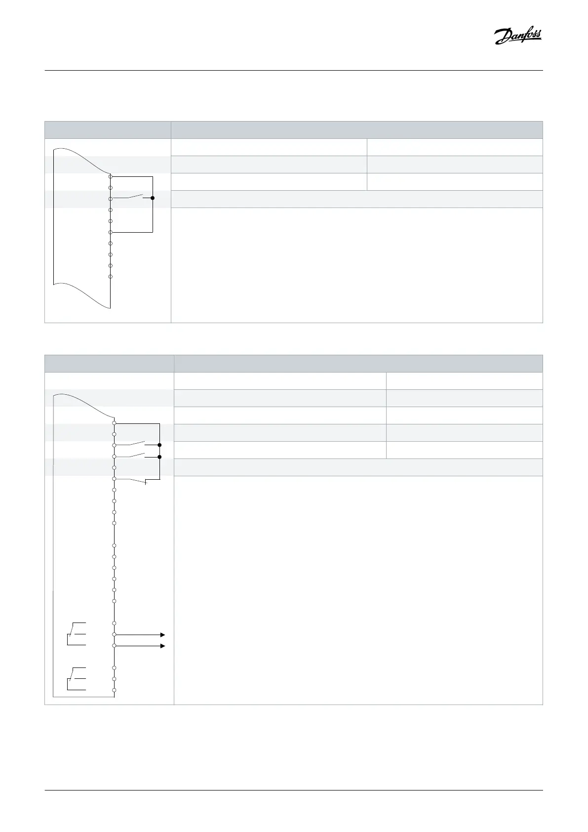
Table 59: Wiring Configuration for Run/Stop Command without External Interlock
Parameter
+24 V
+24 V
D IN
D IN
D IN
COM
D IN
D IN
D IN
D IN
e30bu082.10
XD2.10
XD2.11
XD2.12
XD2.13
XD2.18
XD2.14
XD2.15
XD2.16
XD2.17
XD2.19
Function Setting
Parameter 5-10 Terminal 18 Digital Input [8] Start*
Parameter 5-12 Terminal 27 Digital Input [7] External interlock
*=Default value
Notes/comments:
If parameter 5-12 Terminal 27 Digital Inputs is set to [0] No operation, a jumper wire to terminal
XD2.14 is not needed.
D IN 37 is an option.
Terminal 18 in the parameter title corresponds to terminal XD2.12 in the control compartment.
Terminal 27 in the parameter title corresponds to terminal XD2.14 in the control compartment.
Table 60: Wiring Configuration for Run Permissive
Parameter
A IN
A IN
COM
A OUT
COM
R1
R2
XD2.16
XD2.17
XD2.19
XD2.6
XD2.7
XD2.8
XD2.9
XD2.5
XD2.4
XD2.21
XD2.22
XD2.23
XD2.24
XD2.25
XD2.26
Function Setting
Parameter 5-10 Terminal 18 Digital Input [8] Start*
Parameter 5-11 Terminal 19 Digital Input [52] Run permissive
Parameter 5-12 Terminal 27 Digital Input [7] External interlock
Parameter 5-40 Function Relay [167] Start command act.
*=Default value
Notes/comments:
D IN 37 is an option.
Terminal 18 in the parameter title corresponds to terminal XD2.12 in the control compartment.
Terminal 19 in the parameter title corresponds to terminal XD2.13 in the control compartment.
Terminal 27 in the parameter title corresponds to terminal XD2.14 in the control compartment.
Wiring Configuration Examples
Operating Guide | VLT® AQUA Drive FC 202
AQ262141056213en-000101 / 130R0882
116 | Danfoss A/S © 2018.10

 Loading...


