Table 62: Wiring Configuration for Pulse Start/Stop
Parameter
+24 V
+24 V
D IN
D IN
D IN
COM
D IN
D IN
D IN
D IN
XD2.12
XD2.13
XD2.18
XD2.14
XD2.15
XD2.16
XD2.17
XD2.19
Function Setting
Parameter 5-10 Terminal 18 Digital Input [9] Latched Start
Parameter 5-12 Terminal 27 Digital Input [6] Stop Inverse
*=Default value
Notes/comments:
If parameter 5-12 Terminal 27 Digital Input is set [0] No operation, a jumper wire to terminal XD2.14
is not needed.
D IN 37 is an option.
Terminal 18 in the parameter title corresponds to terminal XD2.12 in the control compartment.
Terminal 27 in the parameter title corresponds to terminal XD2.14 in the control compartment.
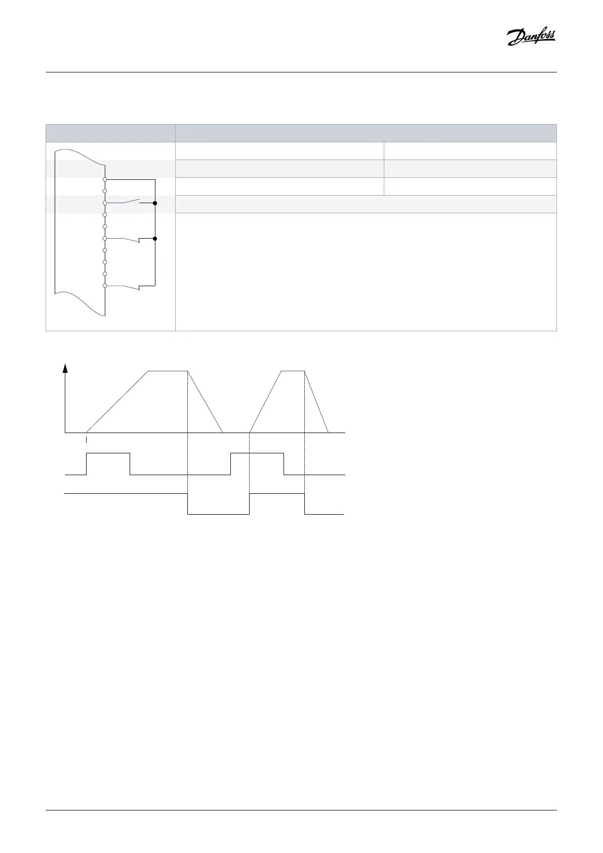
Speed
e130bu087.10
Latched Start (XD2.12)
Stop Inverse (XD2.14)
Illustration 62: Latched Start/Stop Inverse
Wiring Configuration Examples
Operating Guide | VLT® AQUA Drive FC 202
AQ262141056213en-000101 / 130R0882
118 | Danfoss A/S © 2018.10

 Loading...


