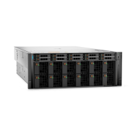
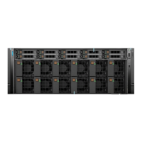
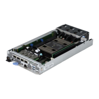
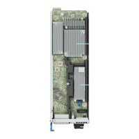
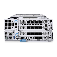
Figure 78. BOSS-N1, Right and Left Control panels, Intrusion switch cable connections from the Storage tray
connecting on the System board for NVIDIA GPU Configurations
NOTE: Make sure you route the VGA connector, BOSS module signal cable, BOSS module power connector on system
board via Processor 1 turtle shell.
NOTE: Make sure you route the Intrusion switch connector on system board via processor 2 turtle shell.
Order From To
1 MB-BOSS_PWR (BOSS module power
connector on system board)
BOSS-BOSS_PWR (BOSS module
power connector)
2 MB-SL16_PCH_PA9 (BOSS module
signal cable on system board)
BOSS-CTRL_DST_PA1 (BOSS module
signal connector)
3 RIO-INTRUSION_DET1 (Intrusion switch
connector on system board)
Intrusion Switch
4 MB-LFT_CP (Left control panel
connector on system board)
Left EAR (Left Control Panel)
5 MB-RGT_CP (Right control panel
connector on system board)
Right EAR (Right Control Panel)
6 MB_FRONT_VIDEO (VGA connector on
system board)
VGA port
7 MB_DSL1 (System board signal
connector)
MB_SL15 (System board signal
connector)
8 RIO-J6 (CPU cool plates connector on
system board)
CPU Cool Plates
108 Installing and removing system components

 Loading...

