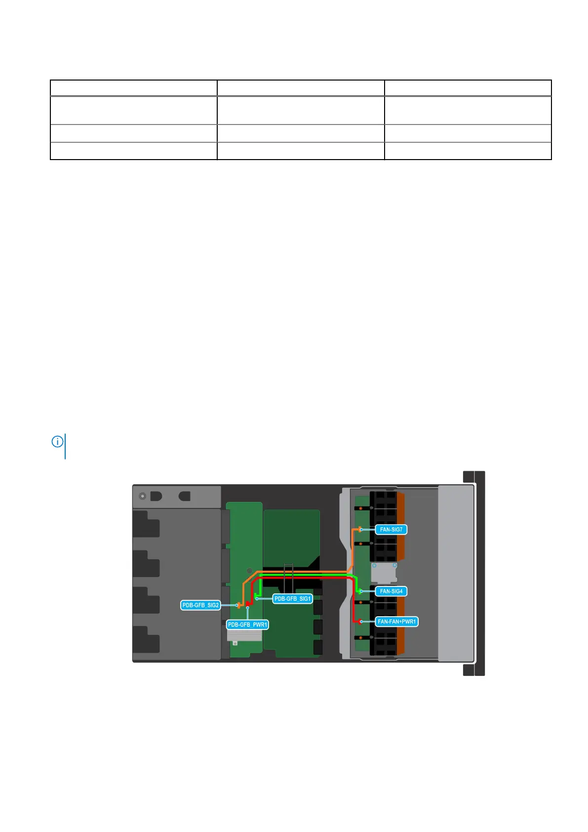
Table 61. Fan cable connections
Order From To
1 PDB-GFB_PWR1 (Power Distribution
Board (PDB) power connector)
FAN-FAN+PWR1 (System fan power
connector)
2 PDB-GFB_SIG1 (PDB signal cable) FAN-SIG4 (System fan signal cable)
3 PDB-GFB_SIG2 (PDB signal cable) FAN-SIG7 (System fan signal cable)
Next steps
Replace the cooling fan board.
Installing the cooling fan board for NVIDIA GPU configurations
Prerequisites
1. Follow the safety guidelines listed in the Safety instructions.
2. Follow the procedure listed in Before working inside your system.
3. Remove the cooling fan modules.
4. Remove the cable cover.
5. Observe and disconnect the intrusion switch bridge cable from the connectors on the storage tray that is connected from
the system board. Observe and disconnect the drive backplane cables, BOSS power and signal cables, fan board cables from
the connector on the storage tray, signal cable from the connectors on the PDB2 and then keep the cables away from the
storage tray. Disconnect the VSB power cables (left and Right) from the connector on the system board and keep them on
the storage tray.
Steps
1. Reconnect the fan cables on the PDB of the bottom layer. Install the system board tray. Install the storage tray. Reconnect
the fan board cables on the fan board into the storage tray.
NOTE:
This step is optional. Reconnect the fan board cables from the PDB of the bottom layer unless it is required to
replace the cables.
Figure 32. Fan cables connection of the Storage tray on the bottom layer of the PDB
74
Installing and removing system components