Removing the drive backplane for Intel GPU configurations
Prerequisites
CAUTION: To prevent damage to the drives and backplane, remove the drives from the system before removing
the backplane.
CAUTION: Note the number of each drive and temporarily label them before you remove the drive so that you
can reinstall them in the same location.
NOTE: The procedure to remove the backplane is similar for all backplane configurations.
1. Follow the safety guidelines listed in the Safety instructions.
2. Follow the procedure listed in the Before working inside your system.
3. Remove the drives.
4. Remove the cable cover.
5. Remove the turtle shell.
6. Observe and disconnect the drive backplane cables from the backplane and signal and power cables from the system board.
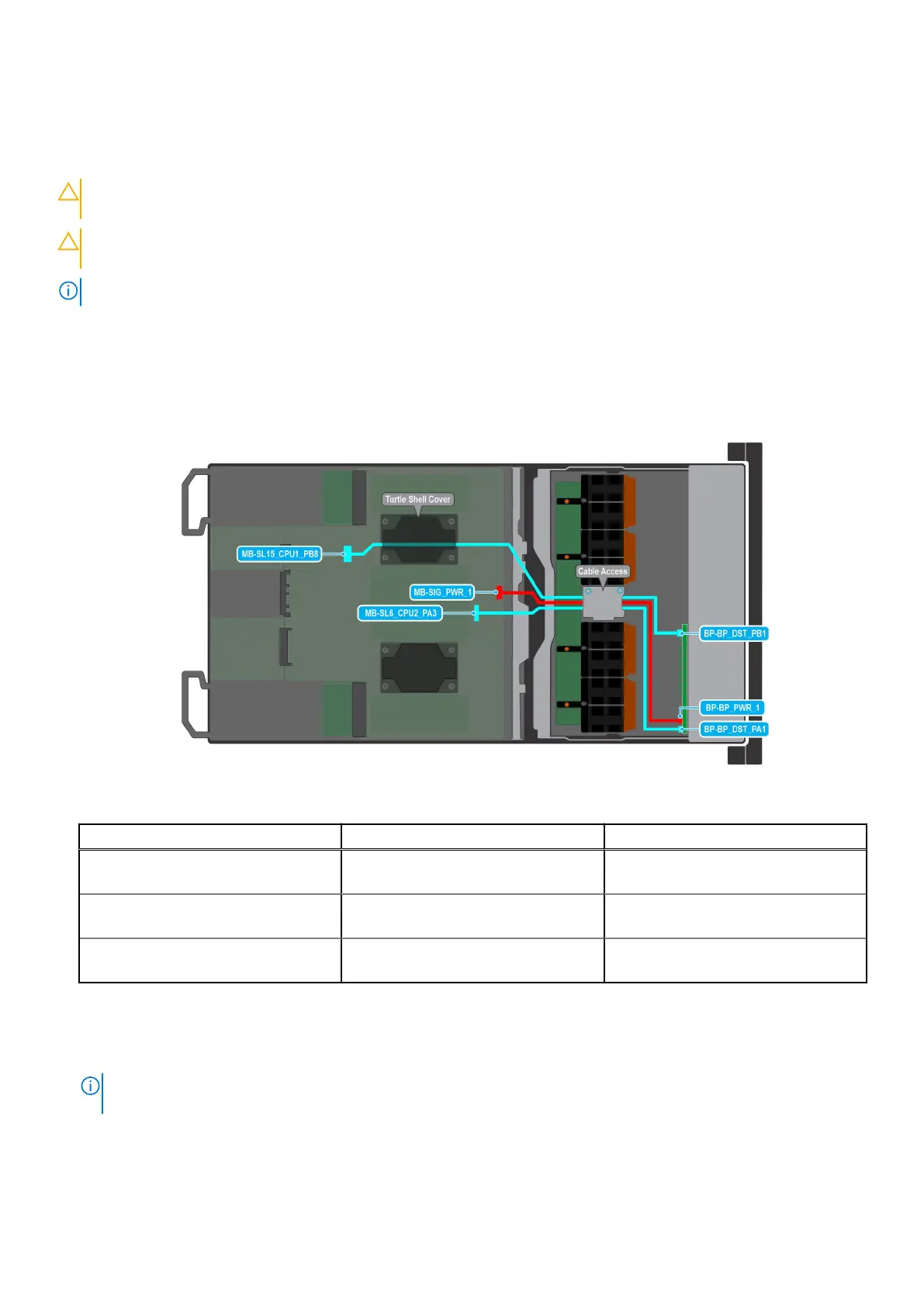
Figure 41. Cabling diagram
Order
From To
1 MB-SL6_CPU2_PA3 (signal connector
on system board)
BP-BP_DST_PA1 (backplane signal
connector )
2 MB-SIG_PWR_1 (system board power
connector)
BP-BP_PWR_1 (backplane power
connector)
3 MB-SL15_CPU1_PB8 (signal connector
on system board)
BP-BP_DST_PB1(backplane signal
connector)
Steps
1. Press the release tab to disengage the drive backplane from the hooks on the system.
2. Lift and pull the drive backplane out of the system.
NOTE:
To avoid damaging the backplane, remove the disconnected backplane cables from the cable routing clips before
removing the backplane.
Installing and removing system components 81