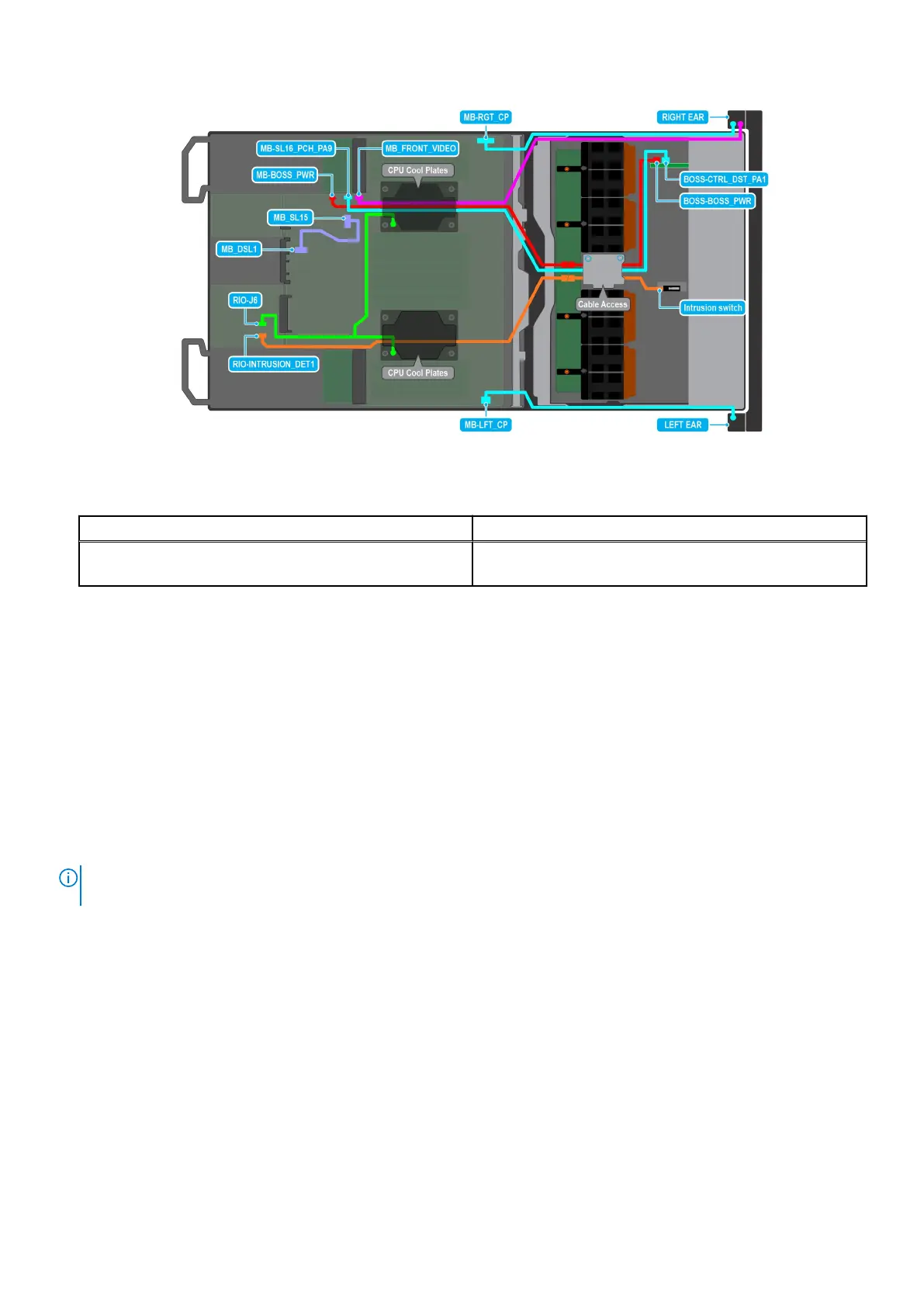
Figure 129. Intrusion switch cabling diagram for NVIDIA GPU configurations
Table 71. Intrusion switch cable connections
From To
RIO-INTRUSION_DET1 (Intrusion switch connector on
system board)
Intrusion Switch on the Storage tray
Next steps
Replace the intrusion switch module.
Installing the intrusion switch module
Prerequisites
1. Follow the safety guidelines listed in the Safety instructions.
2. Follow the procedure listed in Before working inside your system.
3. Remove the cable cover.
4. Remove the riser 4A for Intel GPU configurations or Remove the riser 4B for NVIDIA GPU configurations.
5. Remove the turtle shell from the DLC module 2.
NOTE:
Ensure that you note the routing of the cable as you remove it from the system board. Route the cable properly
when you replace it to prevent the cable from being pinched or crimped.
Steps
1. Align and slide the intrusion switch module into the slot in the system until firmly seated.
2. Using a Phillips 2 screwdriver, tighten the screw on the intrusion switch module.
3. Connect the intrusion switch cable to the connector on the system board. Ensure to route the cable through the DLC
module 2 below the turtle shell.
Installing and removing system components
147