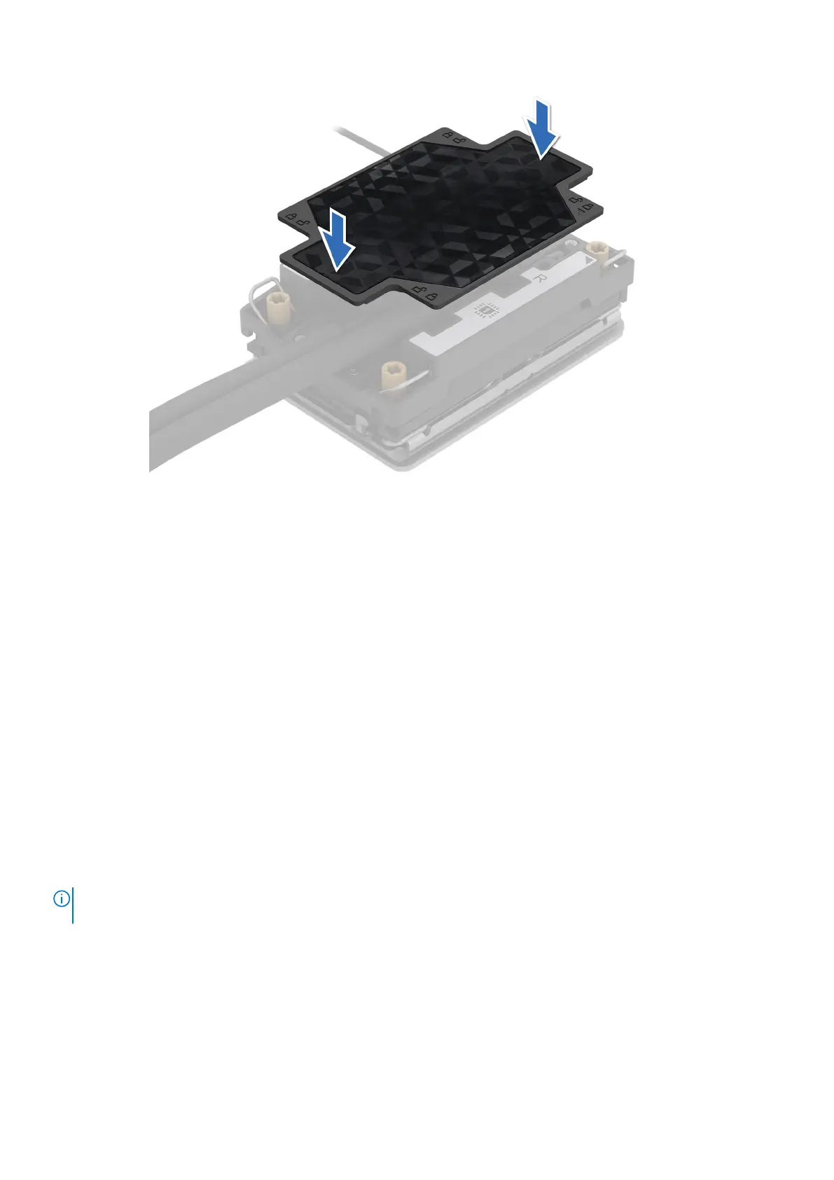
Figure 126. Install the turtle shell
Next steps
1. Install the lower brace cover for Intel GPU configurations or Install the lower brace cover for NVIDIA GPU configurations .
2. Install the storage tray for Intel GPU configurations or Install the storage tray for NVIDIA GPU configurations .
3. Follow the procedure listed in the After working inside your system.
Intrusion switch
This is a service technician replaceable part only.
Removing the intrusion switch module
Prerequisites
1. Follow the safety guidelines listed in the Safety instructions.
2. Follow the procedure listed in the Before working inside your system.
3. Remove the cable cover.
4. Remove the riser 4A for Intel GPU configurations or Remove the riser 4B for NVIDIA GPU configurations.
5. Remove the turtle shell from the DLC module 2.
NOTE:
Ensure that you note the routing of the cable as you remove it from the system board. Route the cable properly
when you replace it to prevent the cable from being pinched or crimped.
Steps
1. Disconnect the intrusion switch cable from the connector on the system board.
2. Using a Phillips 2 screwdriver, remove the screws on the intrusion switch module.
3. Slide the intrusion switch module out of the slot on the system.
Installing and removing system components
145