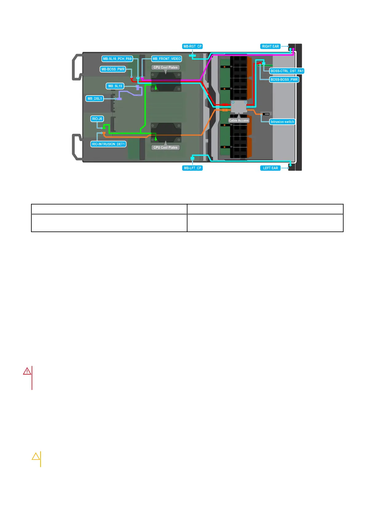
Figure 132. Intrusion switch cabling diagram for NVIDIA GPU configurations
Table 72. Intrusion switch cable connections
From To
RIO-INTRUSION_DET1 (Intrusion switch connector on
system board)
Intrusion Switch on the Storage tray
Next steps
1. Install the riser 4A for Intel GPU configurations or install the riser 4B for NVIDIA GPU configurations.
2. Install the turtle shell on the DLC module 2.
3. Install the cable cover.
4. Follow the procedure listed in After working inside your system.
System battery
This is a service technician replaceable part only.
Replacing the system battery
Prerequisites
WARNING:
There is a danger of a new battery exploding if it is incorrectly installed. Replace the battery only
with the same or equivalent type that is recommended by the manufacturer. Discard used batteries according to
the manufacturer's instructions. See the Safety instructions that came with your system for more information.
1. Follow the safety guidelines listed in the Safety instructions.
2. Follow the procedure listed in the Before working inside your system.
3. Remove the riser 1A for Intel GPU configurations or Remove the riser 1B for NVIDIA GPU configurations.
Steps
1. To remove the battery:
a. Use a plastic scribe to pry out the system battery.
CAUTION:
To avoid damage to the battery connector, you must firmly support the connector while installing
or removing a battery.
Installing and removing system components 149