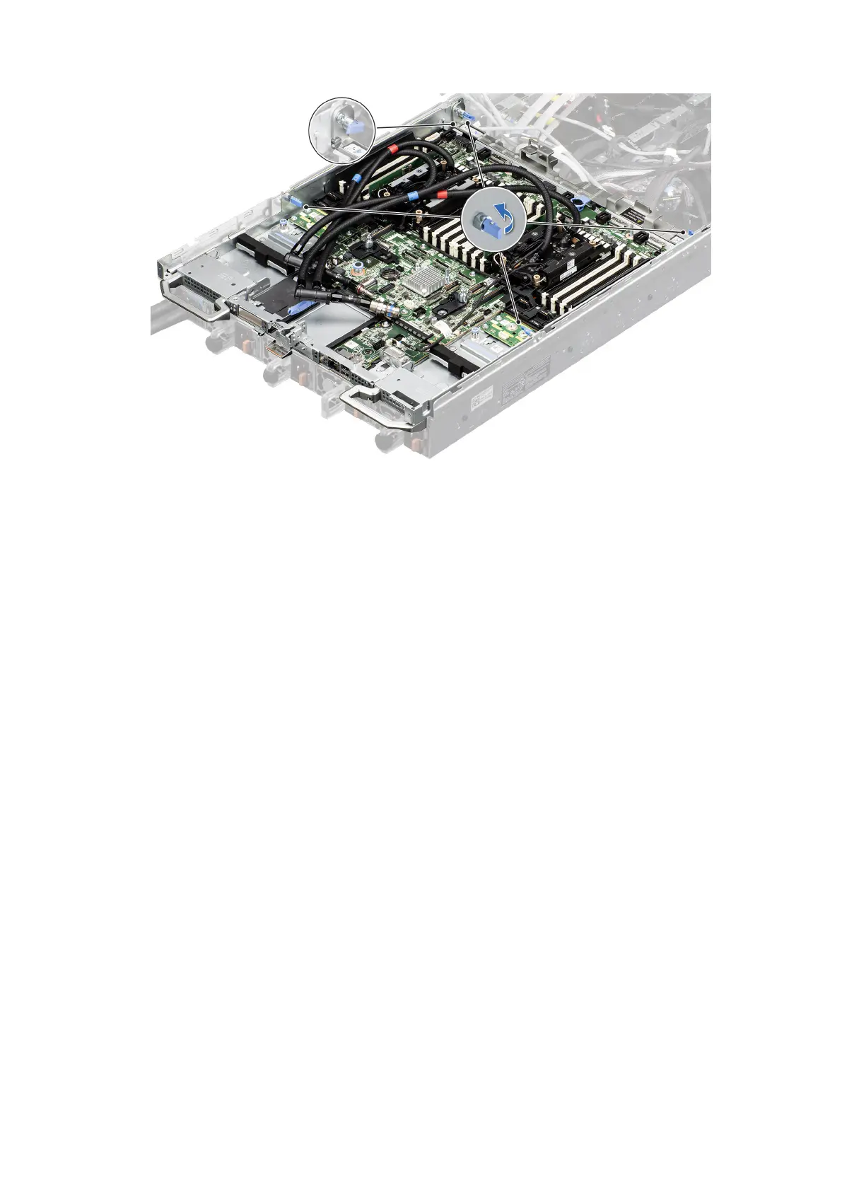
Figure 155. Lock the four blue plungers
Next steps
1. Reconnect the liquid cooling tubes 11 and 12 from the Manifold for DLC module.
2. Install the lower brace cover.
3. Reconnect all the cables onto the system board. For more information, see Cabling diagram.
4. Install the Risers.
5. Install the Storage tray .
6. Install the VSB cables on the system board.
7. Follow the procedure listed in the After working inside your system.
.
LOM card and rear I/O board
Removing the LOM card and rear I/O board
Prerequisites
1. Follow the safety guidelines listed in the Safety instructions.
2. Follow the procedure listed in the Before working inside your system.
3. Remove the system board.
Steps
1. Using a Phillips 2 screwdriver, remove the screws that secure the LAN on Motherboard (LOM) card and rear I/O board to
the system board.
2. Holding the edges, pull the LOM card or rear I/O board to disconnect from the connector on the system board.
170
Installing and removing system components