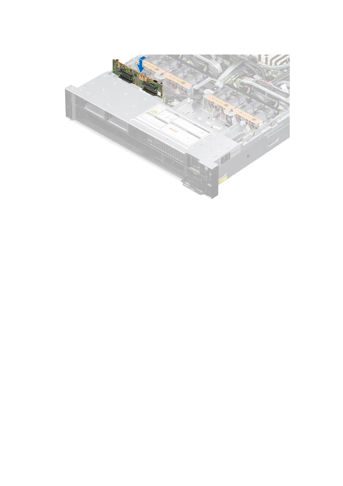
4. Align the slots on the drive backplane with the guides on the system.
5. Slide the drive backplane into the guides and lower the backplane until the blue release tab clicks into place.
Figure 48. Installing the drive backplane
6. Reconnect the backplane cables from the PSB into the backplane of the storage tray. Reconnect the power cable from the
system board into the backplane of the storage tray.
Next steps
1. Install the drives.
2. Reconnect the intrusion switch bridge cable from the storage tray that is connected from the system board. Reconnect the
drive backplane cables, BOSS power and signal cables, signal cable on the PDB2, fan board cables on the connector of the
storage tray. Reconnect the VSB power cables on the system board.
3. Install the cable cover.
4. Follow the procedure listed in After working inside your system.
Optional BOSS-N1 module
Removing the BOSS-N1 card carrier blank
Prerequisites
1. Follow the safety guidelines listed in the Safety instructions.
2. Follow the procedure listed in Before working inside your system.
Steps
Press and pull the BOSS-N1 card carrier blank out from the BOSS-N1 module.
Installing and removing system components
87