5. Remove the storage tray.
6. Remove the risers and keep the risers away from the system board tray and no need to disconnect the cables from the PSB.
7. Disconnect all the cables from the system board and make note of all the cable connections. For more information, see
Cabling diagram.
8. Remove the lower brace bracket.
9. Disconnect the liquid cooling tubes 11 and 12 from the Manifold for DLC module and keep in on the system board and make
sure do not damage any connectors on the system board.
10. Slide out the system board tray.
11. Unplug the GPU cold plate tubes from the Manifold liquid cooling module.
12. Remove the sensor tray.
Steps
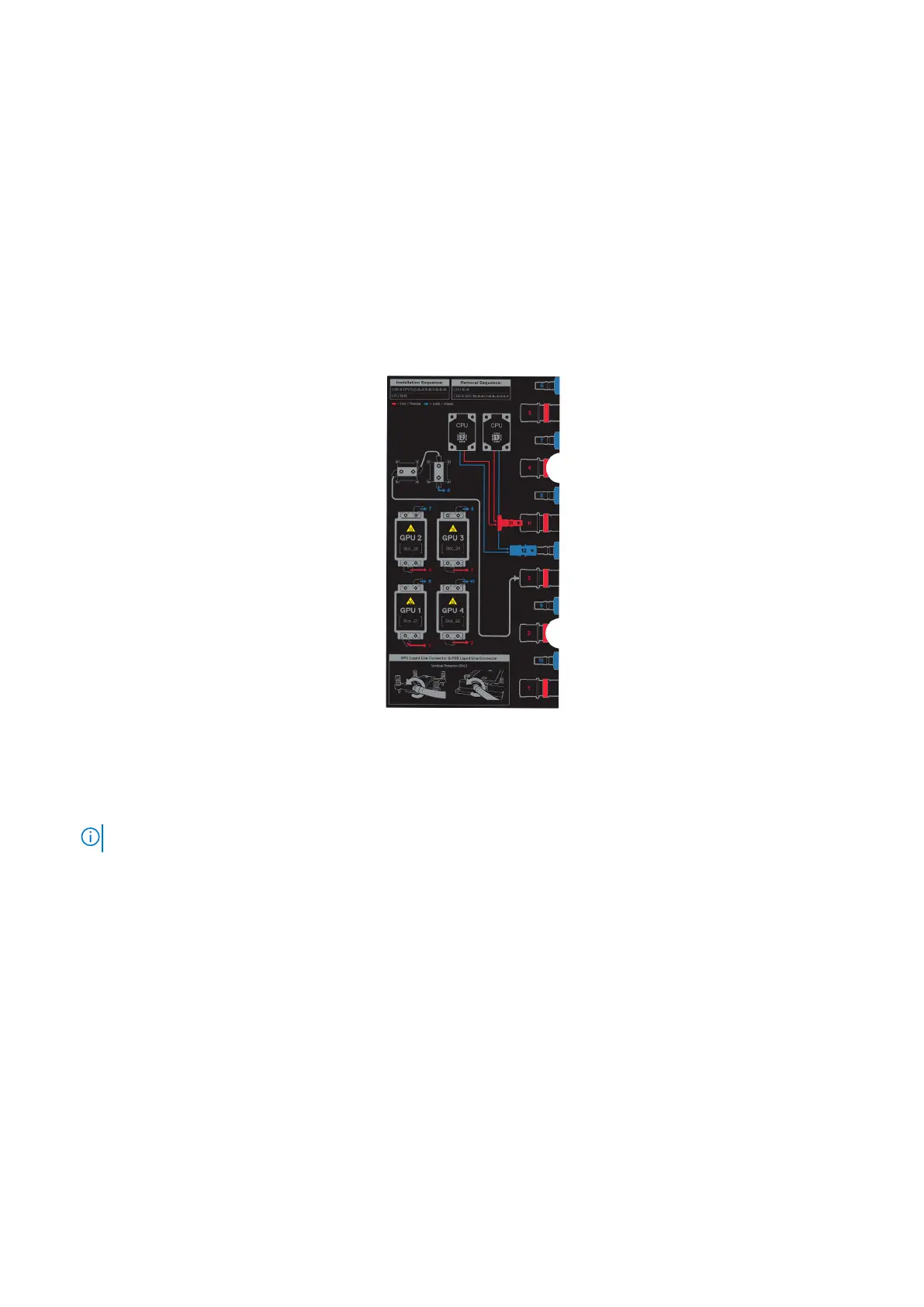
1. Here is the orientation image for removal and installation sequence of liquid cooling tubes for processor, PSB cold plate, GPU
cold plates.
Figure 254. Removal and installation sequence of liquid cooling tubes for processor, PSB cold plate, GPU cold
plates
2. Using the Torx 15, release four screws securing on the GPU with GPU module from the GPU board. Lift and remove the GPU
with GPU module from the GPU socket.
NOTE: The procedure to remove the all the GPU with GPU modules is same.
Installing and removing system components 233